-
-
April 29, 2019 at 2:38 pm
vani
Subscriber
I am doing 2-way transient FSI in ANSYS 19.0 Workbench with Transient structural solver, Fluent and system coupling using a piezoelectrically actuated micropump. I have enabled the ACT piezoelectric and MEMS extension for the piezoelectric actuation.
In transient structural, when setting the actuation voltage with time dependence selected to "YES", a table pops up. The no. of rows in the table is dependant on the no of time steps mentioned in the analysis settings. No of rows in a voltage table cannot be manipulated manually by a user indeed it is automatically manipulated by the Analysis settings.
For a 2 way FSI to be performed in ANSYS using system coupling we cannot define no of time steps to be not more than 1. So this means voltage can only be defined for 1 time step.
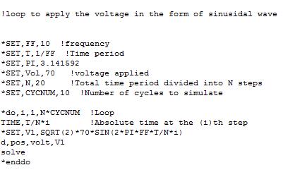
In my case I have to study the influence of driving load applied to the piezoelectrical actuator (Time varying Sinusoidal voltage with a certain frequency) which is mounted onto the micro pump chamber on the flow rate of micropump.
So, I am not sure as what to do for this kind of a problem. Kindly, let me know the solution to this problem.
I am attaching few pictures for better understanding of what I said above.
Best regards
-
April 30, 2019 at 4:02 pm
Hui Liu
Forum ModeratorHi Vani,
Did you try defining the time dependent voltage through command? Use "*DIM" command to first define a table array, and then "D" command to define voltage using the table?
-
April 30, 2019 at 7:35 pm
vani
SubscriberHello HuiLiu,
I did trying that but it did not work for a 2 way FSI. Since even if we define no of steps and time via apdl commands for voltage in Transient structural solver, we are suppose to enter those same time steps in Analysis settings and the problem is same as mentioned above again. ANSYS allows only 1 time step in its solver.
Is there any other way or am I missing out some logic while writing apdl commands because I have least knowledge of commands.But I tried implementing them.
Best regards
vani
-
April 30, 2019 at 8:07 pm
jj77
SubscriberYou do not need to do that and you can do like that.
As said by HuiLiu one needs an array holding the sinus function - finally this is used in the d command.
Below a saw-tooth periodic function with a period of 1 s, and amplitude of 1 V is applied to a named selection called pos, that is what you need, no for loops.
(see here on a detailed descr.: https://www.ozeninc.com/apdl-arrays-tables-quickreference/)
*dim,tabvolt,table,5,,,time
tabvolt(1) = 0,1,0,-1,0 ! time
tabvolt(1,0) = 0,0.25,0.5,0.75,1 ! voltage
! Apply time varying voltage
d,pos,volt,%tabvolt%
-
May 2, 2019 at 10:03 am
vani
SubscriberHello jj77,
Thank you so much for your suggestion. I tried implementing your code, it is working as I wanted.
I have also gone through the link which you attached in your message and also through ANSYS Apdl manual.
I want to ask you a question, above written code is for a single step which is divided into 5 substeps each of size 0.25s. And the corresponding load is divided into these 5 substeps in a one single step. How can we implement this code for multiple steps ? If we can implement through apdl commands then do we need to also change analysis settings accordingly ?
Another question is as you can see, the output is obtained from the 2nd step i.e., from 0.25 s, how can I get response from 0 s i.e., from step 1.
Thanking you
Best regards
Vani
-
- The topic ‘Time dependant voltage load’ is closed to new replies.


-
4893
-
1587
-
1386
-
1242
-
1021

© 2026 Copyright ANSYS, Inc. All rights reserved.


