-
-
May 8, 2026 at 2:41 pm
MEGHAL.CHHATBAR
SubscriberI am developing an ANSYS Mechanical model of a thin flexible plate (SHELL181 elements) with free boundary conditions. Gravity is applied over the entire plate. To simulate handling, I apply equal and opposite distributed pressure over four symmetrically placed patches so that the total force balances gravity and induces bending deformation.
The goal is to use this ANSYS model as a reference (ground truth) to validate a Kirchhoff–Love plate PDE model implemented in MATLAB. The geometric discretization and parameters are kept consistent between base model and ANSYS.
In the base model:
- Linear Kirchhoff plate formulation (no geometric nonlinearity)
- Viscous damping proportional to velocity, normalized as:C/D=5 and constant on all nodes
to match steady-state deformation and damping behavior with ANSYS,
1. How can I select Rayleigh damping (specifically stiffness-proportional coefficient (β) in ANSYS transient analysis to match the base model damping term C/D=5 which is normalized by plate stiffness?
2. Should I use Static Structural or Transient analysis? Which is more appropriate for validating a linear plate model?
3. The structure is unconstrained, so I use weak springs: Without weak springs --> solution fails & with large deflection ON --> solution does not convergeIs it appropriate to:
- keep weak springs ON
- keep large deflection OFF (to remain consistent with linear theory)?
4. Upward prressure:
- Distributed pressure on patches introduces a small imbalance (~1e−3 N in Z)
- Remote displacement (Z=0, rotations free) produces different deformation
Which approach is physically more appropriate for representing gripper action in this case?
5. Current results:
- Max deflection ≈ 0.198 m (consistent in static and transient analysis with β = 0.75)
What are recommended criteria or checks to ensure that:
- the force balance is correctly represented
- the deformation result is physically consistent and suitable as a reference for validating a reduced-order plate model?
-
May 9, 2026 at 1:16 am
peteroznewman
SubscriberMost FEA software developers have benchmark problems that have an analytical solution to check that their finite element code produces numerical results with very small errors relative to the analytical solution. These benchmark problems have boundary condtions that tie the mesh to ground so that the matrix equation does not become ill-conditioned. An organization called NAFEMS publishes a suite of benchmarks that many different FEA software companies use to test their finite element code. https://www.nafems.org/publications/code-verification/
Ansys provides their NAFEMS benchmarks here: https://ansyshelp.ansys.com/public/account/secured?returnurl=//Views/Secured/corp/v252/en/ans_vm/Hlp_V_CH4_1.html
One of the NAFEMS benchmark models is the LE1 – Elliptic Membrane described here. Note that the error between the analytical solution and the finite element solution is mesh dependent. Altair has a whole table of results for different mesh densities and element shapes for this benchmark. Ansys provides a mesh for this benchmark in a .cbd file with their results for the APDL solver.
Since you are developing finite element code in matlab, I suggest you use these benchmarks rather that make up your own model in Ansys.
One part of your plan that is a bad idea is to try to balance applied forces with gravity forces resulting in a floating structure and use weak springs so that you get a solution. This is a bad idea because it create an ill-conditioned system of equations during the solving process. It is a much better idea to use displacement boundary conditions and applied forces because you get a well-conditioned system of equations to solve. Here is what ChatGPT has to say about that.
-
May 10, 2026 at 8:59 pm
MEGHAL.CHHATBAR
SubscriberThank you very much for your prompt and detailed response, and for taking the time to explain this so clearly. It helped a lot.
I would like to clarify my understanding of the validation approach and the suggestion to use benchmark problems.
From my understanding, benchmark problems (e.g., NAFEMS) are mainly used to verify whether a numerical implementation (e.g., MATLAB Crank–Nicolson discretization) is mathematically correct.
However, in my case, the MATLAB model is already based on the formulation from the reference paper (), where the parameters are normalized (e.g., ρ(mass per unit area)/D(stiffness) = 2), and my goal is not to verify the discretization itself but to calibrate the stiffness parameter using ANSYS as a reference.
So my current approach is:- Use ANSYS as a “ground truth” model with physical parameters (E, ρ, ν, h)
E = 7 × 10^10 Pa
ρ = 2700 kg/m³
h = 0.00046 m
ν = 0.3
- Ensure these parameters satisfy the normalized ratio used in MATLAB (ρ/D = 2)
- Apply the same loading scenario (gripper patches + gravity)
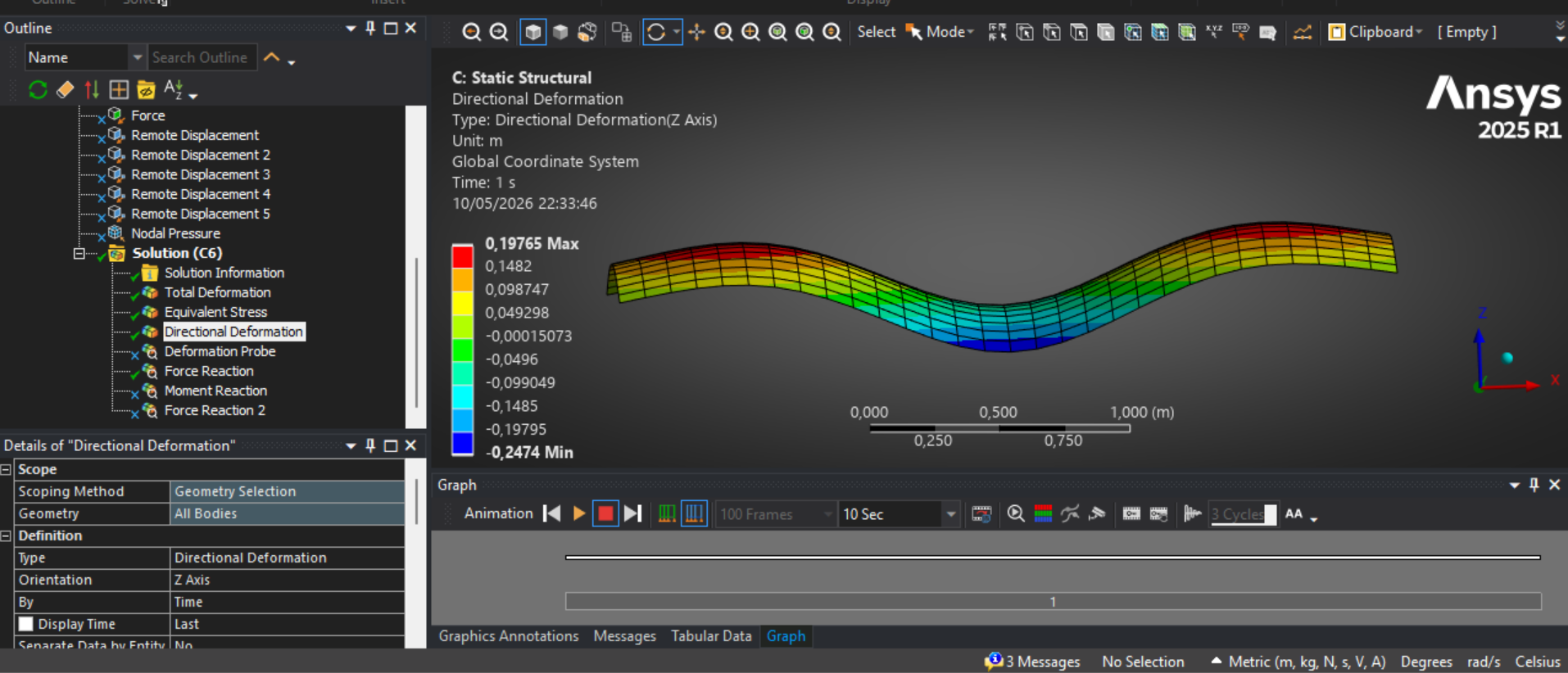
- Compare steady-state deformation
- Tune a stiffness scaling factor in MATLAB until the deformation matches ANSYS
My questions are:
1) Is it correct that benchmark problems are not necessary for my current goal (since I am not validating the numerical scheme, but calibrating model parameters)?
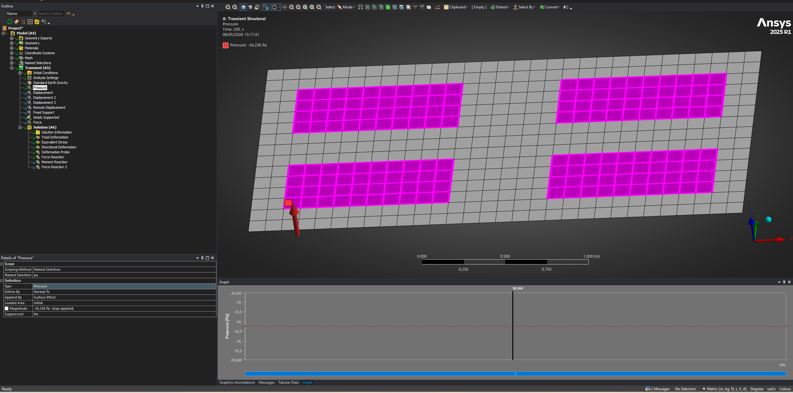
2) In the MATLAB model, the boundary conditions are fully free, and gravity is balanced by upward forces applied over four symmetric patches (gripper regions).
To replicate this in ANSYS, I considered two approaches:
- Applying distributed pressure over the same four patches (to balance gravity), with weak springs enabled for stabilization- Applying remote displacement at the four patches (Z displacement fixed, rotations free)
Which approach is physically correct and more appropriate for this scenario of distributed pressure with weak springs, or remote displacement constraints or other which I should explore?If you need any additional information, I will provide it promptly. I am currently exploring applicable options, and your guidance is extremely helpful in clarifying the right direction.

-
- You must be logged in to reply to this topic.
-
6379
-
1906
-
1457
-
1308
-
1022
© 2026 Copyright ANSYS, Inc. All rights reserved.
