
TAGGED: ansys-mechanical, contact, convergence, static-structural, workbench
-
-
September 8, 2020 at 1:36 pm
Bukovnik
SubscriberHello,
for the past few months I've been working on non linear rotor analysis. Rotor consists of polymer and metal parts. Polymer part is on the outskirt. Electrometal plate is on the inside, while magnet is inserted in electrometal plate.
Whole rotor is then spinning with 6200 RPM (ideally I want to make this number 25 000 RPM) at the temperature of 160°C. Due to spinning and "centrifugal" force, magnets are then pushed away from the center of rotation and thus pressing on the polymer part. For that I've assign a static structural analysis with 2 step analysis.
In the first step I heat up the whole rotor from room temperature to 160°C. After that I assigned rotational velocity for whole rotor, while keeping the temperature at 160°C from first load step.
My points of interests are radial displacements on polymer part (due to spinning + pressure of the magnets) and of course stresses (von Mises).
I managed to get simulation working. While radial displacements seem reasonable, the stresses are far from it and are way higher than one should expect ranking at ~6 000 MPa on electrometal plate and ~1 000 MPa on polymer part in contact region. I believe it is some sort of "singularity of contacts". I tried to run simulation without load step 1, so without heating the rotor up and the stresses were much lower ranking at ~5MPa on electrometal plate.
All of my parts are connected via frictional contacts as that is the real case. I've also set all the things needed to perform non-linear analysis such as: turn Large deflection on, setting Initial, Min and Max substeps, also checked N-R residuals plot. Load step 1 has 100 initial substeps, 20 Min and 1000 Max. Load step 2 has 50 initial substeps, 20 Min and 500 Max.
I believe I am doing something wrong. So far I've tried alot of things:
-modifying Normal stiffness
-trying different Contact formulations
-adding Stability damping effects
-refining mesh
-adding Multilinear isotropic hardening for electrometal plate
None of the above things worked as I hoped. Either high stresses remained or solver couldn't converge.
I did notice that high stresses occur between the electrometal plate and polymer part - mostly on the edge of these two. I believe the problem is in either contact stiffness or penetration, but sadly I don't know how to solve these two in a way I want. Most of the things I tried I found here, on Ansys forum. During the analysis I also received "Contact status has experienced an abrupt change". Solver output also keeps giving warnings about too much penetration.
When looking at the Force convergence plot I usually note that Force convergence line sometimes appears to be below Force criterion for several substeps in a row, yet I don't see the green line marking that Substep converged.
I am also adding the analysis file for anyone willing to take a look and suggest what actions should I take.
Here is the full model, electrometal plate being gray, polymer part being green. Between the two is the magnet on next image being blue.
September 9, 2020 at 10:47 amAshish Khemka
Forum ModeratorHi,nnThe stresses can be because of singularity. For convergence tips please see if following post looks useful nRegards,nAshish KhemkanSeptember 9, 2020 at 3:39 pmSubscriberthank you for your time and effort. Either you forgot to post the link or I cannot see it for some odd reason.nSeptember 10, 2020 at 4:29 amForum ModeratorSeptember 10, 2020 at 3:23 pmpeteroznewman
Subscriber,nThank you for taking the time to make a detailed post. is correct about the stress singularity. To resolve that, one approach is to add a small radius on the sharp interior corner. Another approach is to leave it sharp, but include plasticity in the material model and just let those few elements yield slightly. You will get the same effect with Creep. Those elements will creep much faster than the elements a little further away from the singularity.nIs the Electro metal plate a ferrous metal? If so, isn't the magnet attracted to the plate? The magnetic force pulling the magnet toward the plate could be higher than the centrifugal force pulling the magnet away from the plate and toward the molding. Measure or calculate the magnetic force and compare it with the centrifugal force. If the magnetic force is higher, then use bonded contact between the magnet and the plate on the large flat face.nDon't use a Fixed Support on a cylindrical part that you want to load with a Rotational Velocity. That prevents hoop strain from developing. Delete the Fixed Support.nThe two Frictionless supports on the cut faces are correct. There is only one DOF, the X direction displacement that needs to be constrained. Pick the circular edge of the plate and use a Remote Displacement to set X = 0 and leave all others free. Make sure the remote displacement Behavior is set to Deformable.nIsn't the Injection molded part an insert molding operation? Isn't there adhesion between the PPS and the Electro metal plate? If that was the case, then it would be appropriate to use bonded contact between these parts, or even Shared Topology. If the adhesion is weak, then frictional contact is a good conservative assumption.nLinear Tet elements are not recommended. I changed that to quadratic and suppressed all the mesh controls. The default mesh is a good place to start. I'm running that mesh now in ANSYS 2020 R1 and will post another comment when it finishes. Looking at your N-R Force Convergence plot, this model is converging nicely. There are no issues in that plot.nPlease reply with the version of ANSYS you are using.nSeptember 10, 2020 at 6:42 pmSubscriberArray, Arraynthank for your replies and suggestion.nI've come across the links akhemka posted when I was trying to find a solution. I will take another look at them to see if I missed something. My concern is (correct me if I am wrong) that these are not the usual singularities. Heres why:n-location of these high stresses isn't fixed. I tried different contact modifications and mesh sizes (from coarse to fine) and location on stresses was sometimes shifted few elements towards the edge or away from edgen-value of stresses isn't fixed as well, since the modifications mentioned above gave very different values ranking from 2 000 MPa to 11 000 MPa.nnI tried to add small radius (fillet) on electro metal plate but then I had issues with mesh, since I wasn't able to use structured mesh. Perhaps I should more effort into that. If you by sharp interior corner mean corner on the polymer, then I haven't tried that yet.nI've also tried to include plasticity. I was using bilinear and multilinear isotrophic hardening, for electro metal plate only. The issue I got there was the convergence. Solver stopped at step 1 ~60% load applied. I've even tried to increase initial substeps to 500 and same problem occurred.nIn future I will only include Creep for polymer part, not the metal ones.nThank you for suggestion on support, I will replace it with Remote Displacement. Now I assume you are talking about global coordinate X being 0 right?.ow I am not exactly sure what do you mean by pick the circular edge? Why only edge and now the whole circular face? If it's only edge should I pick upper or lower one? (I'm adding a image for better understanding if that is what you had in mind.)n nnElectro metal isn't isn't ferrous metal, thus there is not magnetic force between magnet and plate.nPolymer is actually injected on magnet/plate. I am not sure about the adhesion. I am running this model for my master thesis and frictional contact seemed like the best option for me.nI assumed eventually I'd have to use quadratic Tet elements, was just avoiding it since they are more time consuming. Thank you for suggestion and taking actions.nThank you a lot for trying and running my analysis.nSide question for N-R plot: between ~60th and ~80th iteration Force convergence was below Force criterion which in my mind means that substep should converge. Each substep on that interval actually. But for some reason there are few substeps that didn't converge? Also what is the phenomenon that the line suddenly drops below Force criterion on that interval? Does it have a meaning at all?nMy version of ANSYS is 2019 R3.nn
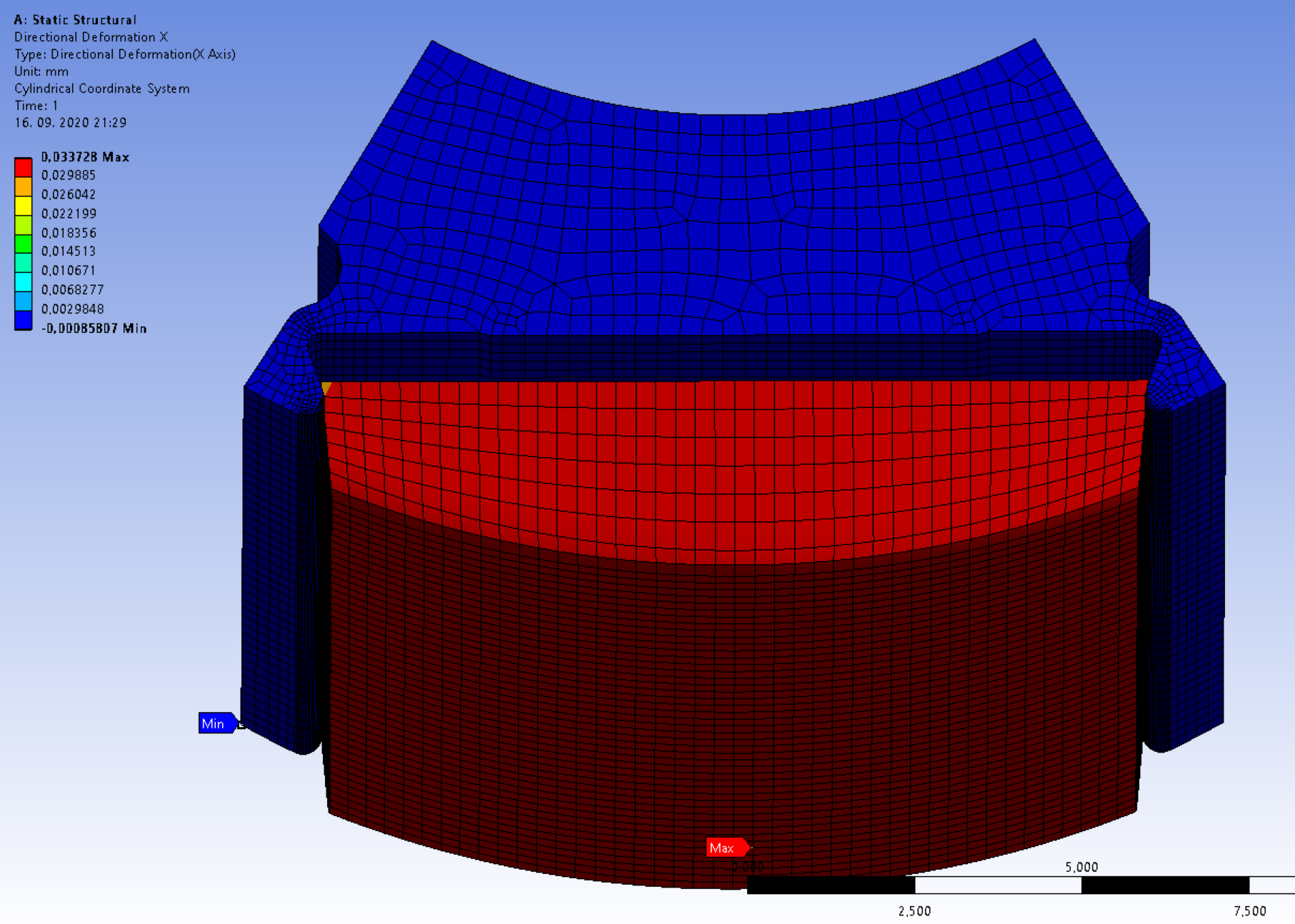
September 10, 2020 at 7:26 pmSubscriber,nYes, the circular edge you show above is what I was suggesting. You could pick the whole flat face at the top or the cylindrical face, but it is not necessary. There are no large forces to ground being developed in the X direction, so there won't be any stress developed as long as you left it Deformable. The solver must see connections to ground in all six DOF. You will get a warning: Not enough constraints appear to be applied... but you can ignore that warning because there are sufficient constraints.nThe fillet radius would be on the interior corner of the polymer, but since it is molded, it would be also on the mating part.nIf you can switch from frictional contact to bonded contact for all faces touching the polymer, that will greatly speed up the solution because far fewer iterations are required compared with frictional contact. Try to find out if there is a surface roughness and cleaning treatment to the metal and magnet parts that will create adhesion during the molding process.nOn the N-R Force Convergence Plot, you will see the Force drop below the Criterion for several iterations because there are several checks on convergence, Force and Displacement for example. If you change to look at the Displacement Convergence, you may find that is above the criterion line while the Force is below the criterion line. The solver keeps going until they are both below the line. It might suddenly drop below the line because a large number of nodes resolved contact in the last iteration and things are in equilibrium.nOne method to reduce the number of iterations when there is a large area of frictional contact is to reduce the contact Normal Stiffness and change the default value of 1 to 0.1 or even 0.01. This allows more penetration, but a very small amount of penetration could be acceptable for the benefit of a faster solution time. I see you used that on one of the contact already with a value of 0.001. Another place that can help in the Contact details is the Update Stiffness to Each Iteration.nAnother useful command is NEQIT,50 so if you see the force convergence plot trending toward the criterion line, and it looked like with a few more iterations, it would cross the line, then suddenly, the solution control logic abandons that substep, and tries at a smaller time step, that command will tell solution control to keep going for 50 iterations instead of the default 26 iteration.nSeptember 11, 2020 at 4:42 pmSubscriberArray ,nI will change the things you are talking above, especially the Support.nThank you for taking your time and explaining the N-R plot in details, makes a lot more sense now. Since it's the tool I use a lot it's nice to get any additional knowledge about it.nIf possible I will avoid adding fillets on edges, since as I said above model then requires much finer mesh to capture those fillets.nYes it's true that I've been using Contact Stiffness of factor 0.001. I've set it only on contact I believe is causing singularities. I am somewhat of afraid changing it, since Solver output keeps giving There is too much penetration line. Yet I agree that small penetration should be acceptable. However to determine how much penetration my model has once analysis is finished I use Contact tool and choose penetration. Hope this is a proper way to clarify if there is too much penetration due to Contact stiffness being too low.nThank you for the NEQIT,50 command and it's explanation. Unfortunately I still don't know how to use APDL commands with workbench. I've been digging a little bit into it (here is the video I've been studying) https://www.youtube.com/watch?v=qqB2HjgmDow. Will definitely use that command in the future!nI did some thought experiment and consider few cases, also asked professor for advice. With all that I believe using Bonded contact is like 90% verified. Electro metal plate has face roughness for sure and polymer is molded directly into it. So by that logic there should be adhesion between the two parts. I will try and run simulation with Bonded contacts between metal and polymer parts tonight and compare the results to the ones where I use frictional contact. I believe good verification for contact to work is if the directional deformation in radial axis is the same or at least nearly close. I will post another comment once I know more.nSeptember 16, 2020 at 7:37 pmSubscriberHello,nnso for the last few days I've been trying to make my model work, sadly without success. Bonded contacts helped, but gave higher radial directional deformation so I am not sure whether I should use them or not.nI decided to take a try on adding s small radius on sharp corners, just like you suggested. The problem occurs when I try to mesh the electro metal plate. Due to small radius I cannot seem to get structural mesh unless I partition that part. I did that in Space claim and set my Topology to be shared, so that nodes would correspond to partitions. After successfully meshing electro metal plate with hex elements I ran the simulation with only magnet and plate. Before that I have also run a simulation with plate and magnet only but without small radius on sharp corners. Here are the mesh and results:n
nnElectro metal isn't isn't ferrous metal, thus there is not magnetic force between magnet and plate.nPolymer is actually injected on magnet/plate. I am not sure about the adhesion. I am running this model for my master thesis and frictional contact seemed like the best option for me.nI assumed eventually I'd have to use quadratic Tet elements, was just avoiding it since they are more time consuming. Thank you for suggestion and taking actions.nThank you a lot for trying and running my analysis.nSide question for N-R plot: between ~60th and ~80th iteration Force convergence was below Force criterion which in my mind means that substep should converge. Each substep on that interval actually. But for some reason there are few substeps that didn't converge? Also what is the phenomenon that the line suddenly drops below Force criterion on that interval? Does it have a meaning at all?nMy version of ANSYS is 2019 R3.nn
September 10, 2020 at 7:26 pmSubscriber,nYes, the circular edge you show above is what I was suggesting. You could pick the whole flat face at the top or the cylindrical face, but it is not necessary. There are no large forces to ground being developed in the X direction, so there won't be any stress developed as long as you left it Deformable. The solver must see connections to ground in all six DOF. You will get a warning: Not enough constraints appear to be applied... but you can ignore that warning because there are sufficient constraints.nThe fillet radius would be on the interior corner of the polymer, but since it is molded, it would be also on the mating part.nIf you can switch from frictional contact to bonded contact for all faces touching the polymer, that will greatly speed up the solution because far fewer iterations are required compared with frictional contact. Try to find out if there is a surface roughness and cleaning treatment to the metal and magnet parts that will create adhesion during the molding process.nOn the N-R Force Convergence Plot, you will see the Force drop below the Criterion for several iterations because there are several checks on convergence, Force and Displacement for example. If you change to look at the Displacement Convergence, you may find that is above the criterion line while the Force is below the criterion line. The solver keeps going until they are both below the line. It might suddenly drop below the line because a large number of nodes resolved contact in the last iteration and things are in equilibrium.nOne method to reduce the number of iterations when there is a large area of frictional contact is to reduce the contact Normal Stiffness and change the default value of 1 to 0.1 or even 0.01. This allows more penetration, but a very small amount of penetration could be acceptable for the benefit of a faster solution time. I see you used that on one of the contact already with a value of 0.001. Another place that can help in the Contact details is the Update Stiffness to Each Iteration.nAnother useful command is NEQIT,50 so if you see the force convergence plot trending toward the criterion line, and it looked like with a few more iterations, it would cross the line, then suddenly, the solution control logic abandons that substep, and tries at a smaller time step, that command will tell solution control to keep going for 50 iterations instead of the default 26 iteration.nSeptember 11, 2020 at 4:42 pmSubscriberArray ,nI will change the things you are talking above, especially the Support.nThank you for taking your time and explaining the N-R plot in details, makes a lot more sense now. Since it's the tool I use a lot it's nice to get any additional knowledge about it.nIf possible I will avoid adding fillets on edges, since as I said above model then requires much finer mesh to capture those fillets.nYes it's true that I've been using Contact Stiffness of factor 0.001. I've set it only on contact I believe is causing singularities. I am somewhat of afraid changing it, since Solver output keeps giving There is too much penetration line. Yet I agree that small penetration should be acceptable. However to determine how much penetration my model has once analysis is finished I use Contact tool and choose penetration. Hope this is a proper way to clarify if there is too much penetration due to Contact stiffness being too low.nThank you for the NEQIT,50 command and it's explanation. Unfortunately I still don't know how to use APDL commands with workbench. I've been digging a little bit into it (here is the video I've been studying) https://www.youtube.com/watch?v=qqB2HjgmDow. Will definitely use that command in the future!nI did some thought experiment and consider few cases, also asked professor for advice. With all that I believe using Bonded contact is like 90% verified. Electro metal plate has face roughness for sure and polymer is molded directly into it. So by that logic there should be adhesion between the two parts. I will try and run simulation with Bonded contacts between metal and polymer parts tonight and compare the results to the ones where I use frictional contact. I believe good verification for contact to work is if the directional deformation in radial axis is the same or at least nearly close. I will post another comment once I know more.nSeptember 16, 2020 at 7:37 pmSubscriberHello,nnso for the last few days I've been trying to make my model work, sadly without success. Bonded contacts helped, but gave higher radial directional deformation so I am not sure whether I should use them or not.nI decided to take a try on adding s small radius on sharp corners, just like you suggested. The problem occurs when I try to mesh the electro metal plate. Due to small radius I cannot seem to get structural mesh unless I partition that part. I did that in Space claim and set my Topology to be shared, so that nodes would correspond to partitions. After successfully meshing electro metal plate with hex elements I ran the simulation with only magnet and plate. Before that I have also run a simulation with plate and magnet only but without small radius on sharp corners. Here are the mesh and results:n
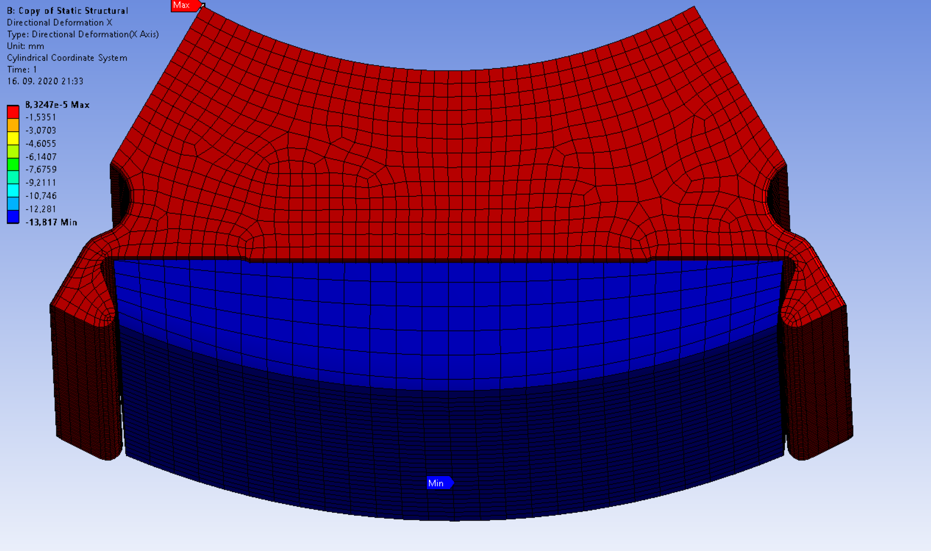
 And here are the mesh and results of exactly same simulation with added fillets (radius on corners) and thus needed partition for successfully meshing:n
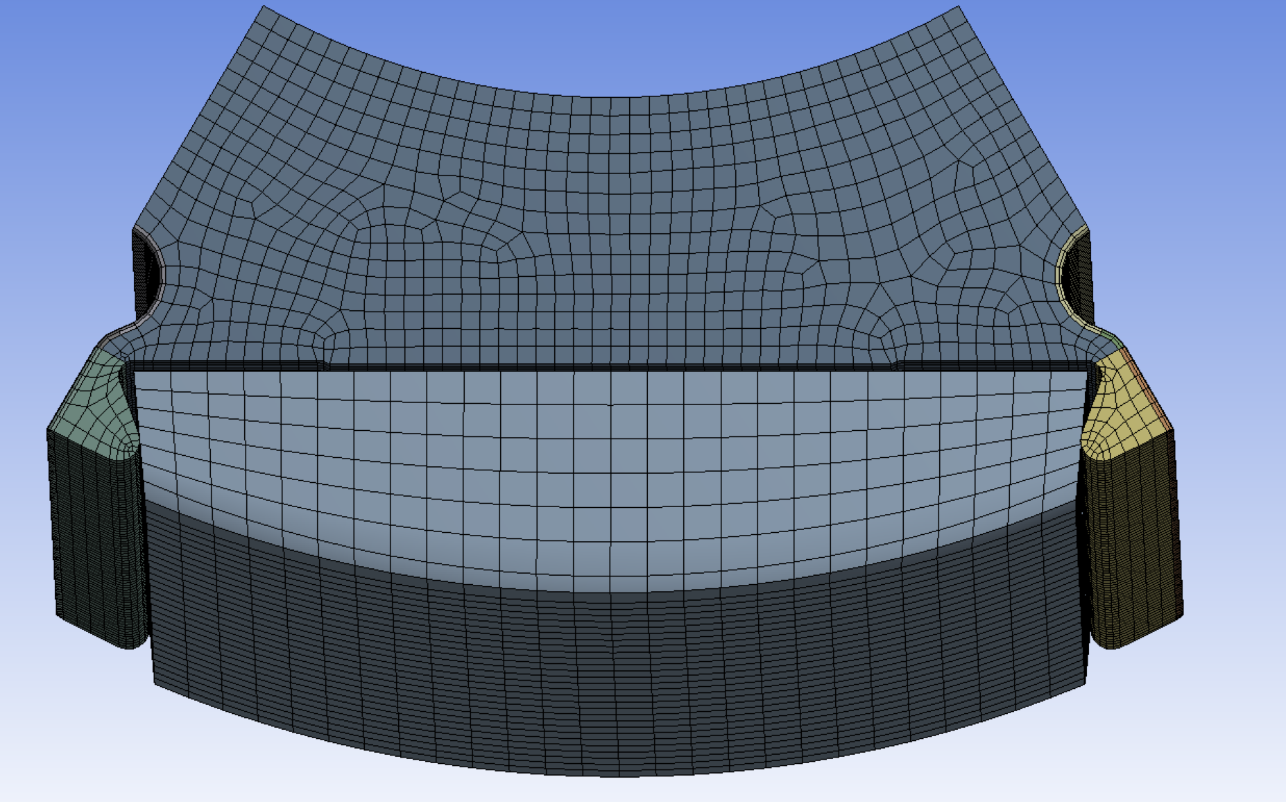
 I really have no logical explanation for this. I double checked everything and tried multiple times with always same results. For a better understanding I am also attaching a model. Any help and tips are appreciated.nnThank you!nn
September 17, 2020 at 10:53 amSubscriberThere is a lot of support missing when you suppress the green injection molding part. With the molding, the fingers around the magnet are supported by a layer of PPS that is in compression between the two fingers, as well as the layer of material that develops hoop stress to support the magnet.n
I really have no logical explanation for this. I double checked everything and tried multiple times with always same results. For a better understanding I am also attaching a model. Any help and tips are appreciated.nnThank you!nn
September 17, 2020 at 10:53 amSubscriberThere is a lot of support missing when you suppress the green injection molding part. With the molding, the fingers around the magnet are supported by a layer of PPS that is in compression between the two fingers, as well as the layer of material that develops hoop stress to support the magnet.n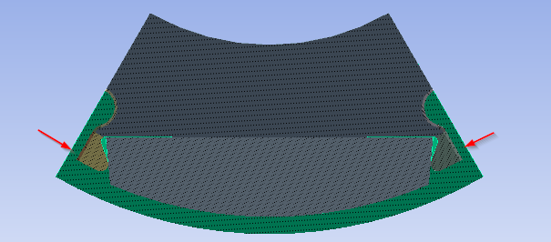 When the injection molding is suppressed, the support retracts to the central core of the electro metal plate and the fingers are free to flex out. This causes high stress due to the small wedge angle on the magnet, and there is no layer on the outside to support the magnet.n
 You need to add a blend fillet to this edge of the injection molded part...n
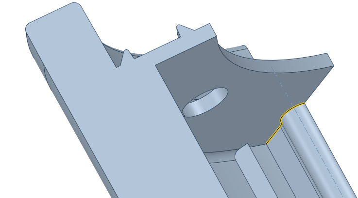 ...to match this fillet on the electro metal plate.n
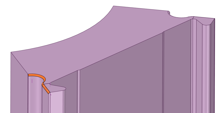 September 17, 2020 at 11:10 amSubscriberthank you for the answer.nHowever I am not sure you understood what I meant. My problem is that adding a small radius (0.05 mm) on the electro metal plate completely changes the behavior of whole model. Despite the similar mesh, results are not logical. On the first result image magnet flies away, as expect. It flies away by 0.033 mm due to centrifugal force. That in my books seems completely logical. However on the second result image the magnet doesn't move at all. Even more It seems like that electro metal plate moves IN magnet and magnet is standing still. To double check: it is completely same simulation with a difference of added small radius in second simulation. I do not know how to explain that behavior.nHope any more tips can be taught of.nThank you.nSeptember 18, 2020 at 4:22 amSubscriberSeptember 18, 2020 at 9:33 amSubscriberPeter I cannot thank you enough for clarifying this for me. Makes more sense now. Currently I am running a simulation with added Injection molded part without thermal condition so far. I've added fillets. If simulation runs well I will added a thermal condition and post results to see if it solves the singularities problem.nViewing 12 reply threads
- The topic ‘Thermomechanical analysis – high stress on contact edges and convergence problems’ is closed to new replies.
Ansys Innovation Space Trending discussions
 Top Contributors
-
peteroznewman
 3572
3572 -
scabo
 1193
1193 -
Dennis Chen
 1076
1076 -
javat33489
 1063
1063 -
Shyam Prasad V Atri
952
Top Rated Tags
© 2025 Copyright ANSYS, Inc. All rights reserved.
Ansys does not support the usage of unauthorized Ansys software. Please visit www.ansys.com to obtain an official distribution.
-


