-
-
August 9, 2024 at 7:59 am
-
August 9, 2024 at 9:50 am
Kaushal Vadnere
Ansys EmployeeHi Ji Shiyu,
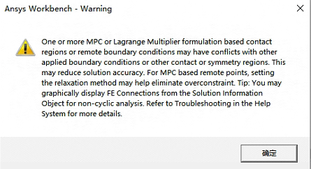
this warning suggests that you have overlapping boundary conditions or contacts which lead to conflicts and prevent MPC constraints from being created and cause parts to lose contacts.
To overcome this, consider relocating applied supports/boundary conditions/contacts sharing same bodies, surfaces, edges, nodes.
Refer to this article in Ansys help for more troubleshooting recommendations: One or more MPC or Lagrange Multiplier formulation based contact may have conflicts (ansys.com)-
August 9, 2024 at 10:07 am
1617836513
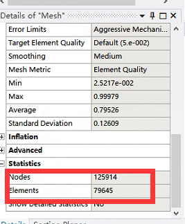
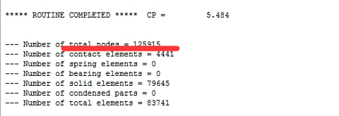
SubscriberYeah you're right. I see by solving the information that it's a problem with where node 125915 is located, but my mesh only generates 125914 nodes, so I can't find where node 125915 is. Why is this?
-
August 9, 2024 at 1:10 pm
Kaushal Vadnere
Ansys EmployeeDo you have a remote point (can be from remote force or displacement as well) in your model?
-
August 9, 2024 at 1:52 pm
1617836513
SubscriberYes, I set up a remote point. Do you mean the remote point is node 125915? I don't see node 125915 in the geometry using the node name search, what should I do to get rid of that warning to improve the calculation accuracy? Thank you!
-
-
-
August 9, 2024 at 2:02 pm
Kaushal Vadnere
Ansys EmployeeYes, the remote point is considered as a node, it is not a geometric node hence you won't be able to see it. To get rid of that warning, I have already answered what you will have to do. If you have applied all the boundary conditions correctly to represent the real life conditions in your simulation (I will still suggest to make sure you don't have any boundary condition and contact definition sharing the same geometric entity), I believe there is no reason to worry about accuracy of results unless the mesh quality is very bad, inappropriate material properties, etc. as this is just a warning and not an actual error. Just wondering, have you got the solution for the problem?
-
August 9, 2024 at 3:36 pm
1617836513
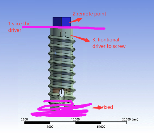
SubscriberUnfortunately there is no solution for now. I don't seem to have permission to view the article you posted. Like the picture I posted, slice the driver in two and set the remote point on the top section while the bottom section establishes contact with the screw. That would be a good way to try it I think? If this works, can the counter moment of the remote point of the count output be used as the maximum screw-in moment of the screw? Thank you sir.
-
August 14, 2024 at 6:32 am
Kaushal Vadnere
Ansys EmployeeYes, you can use moment reaction object and scope it to remote displacement to get the moment required to turn the screw. Also, Is that the only warning or error messages are you getting? As you mentioned your solution is getting failed, it would be also necessary to debug the divergence.
-
-
-
- You must be logged in to reply to this topic.


-
3407
-
1057
-
1051
-
896
-
887

© 2025 Copyright ANSYS, Inc. All rights reserved.


