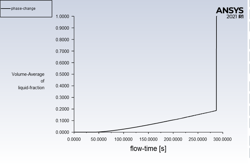
I'm trying to build a basic Fluent phase change model simulating a block of paraffin wax with an aluminum casing inside of a duct with hot air blowing over it at 5 m/s at 350 K. When I run my model, after some time I see a sudden spike/drop in temperature that causes the PCM to jump to fully melted instantly. The PCM is initialized to 288 K, right below the solidus temperature (I tried varying the temperature to be more subcooled, but still had the same issue).
I read through the forum thread here to see if I had any similar issues, but it appeared they solved the same issue by switching to the adaptive time control - CFL based. However, that is the method I've been using since I started. /forum/forums/topic/convergence-issue-in-pcm-simulation-fluent/
I checked my CFL number originally and it was 0.31 (@ a time step of 0.1 sec), I then looked at varying my time step to get the CFL number closer to ~1 and still had the same issue. I then looked at refining my mesh to be much more fine at the original 0.1 sec time step, bringing my CFL closer to ~1, but still had the same issue at roughly the same point. This leads me to believe that my material definition for the PCM may not be correct.
Looking at the time step in the transient simulation right before the error, here is what I noticed:
- Volume average mass fraction: 0.2
- Volume average temperature: 290.52 K
- PCM center point temperature 290.15 K (right at solidus temperature, theoretically in the mushy zone)
- Max mass fraction is 0.68 right in the hot corners (temperature at this location is 308.8 K, much higher than liquidis temperature of 292.15 K)
Is anything that I'm attempting that is glaringly incorrect? Here is the background on my simulation.
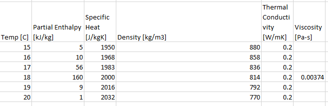
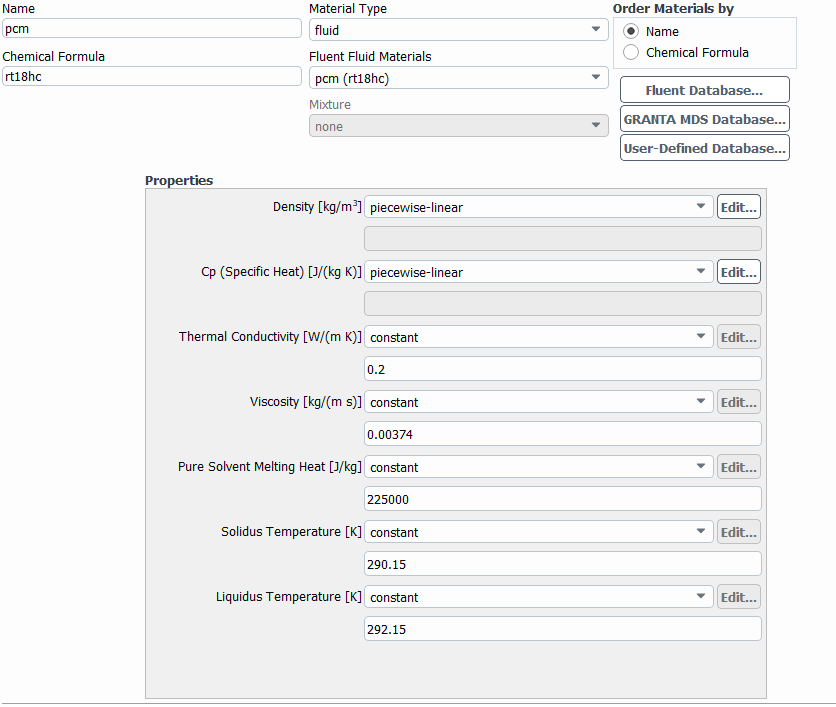
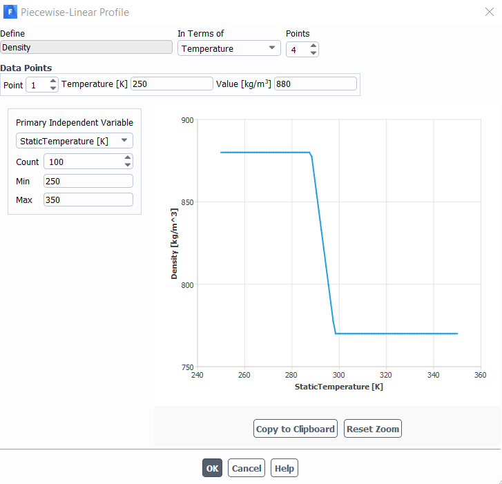
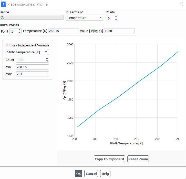
Material properties of paraffin:
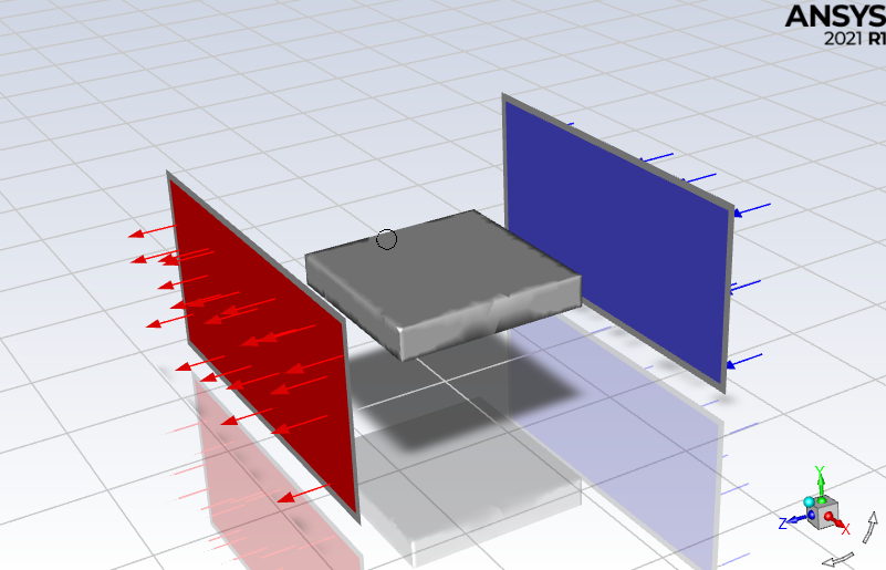
Side walls of duct hidden, PCM block with air flow around it:
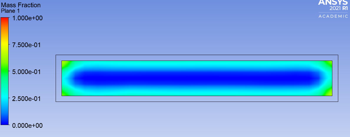
YZ plane view of mass fraction in time step right before error (0.68 mass fraction in the corners, 0 in the center)
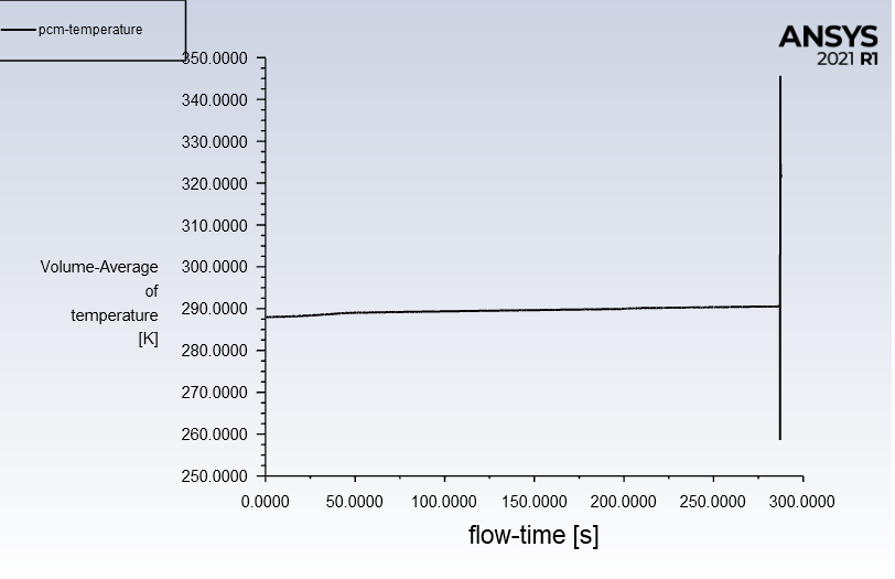
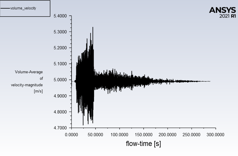
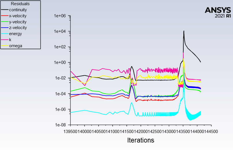
Liquid fraction, PCM temperature, average air flow velocity over simulation time, and residuals:
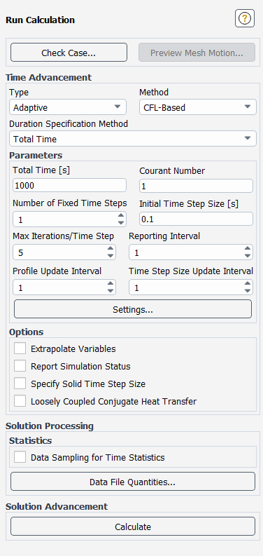
Simulation controls and material properties for PCM:
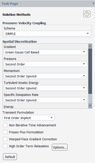
(Energy is also Second Order Upwind)


