TAGGED: bonded-contact, fixed-joint, mechanical
-
-
June 23, 2023 at 4:26 am
Sizhe Ma
SubscriberHi all,
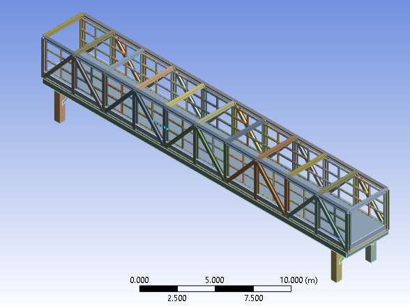
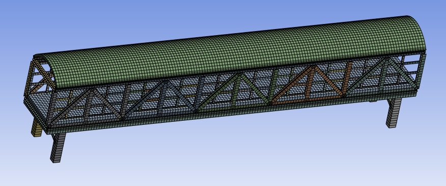
I made a post a few days ago asking about how to ensure contacts are all made properly; thanks to Peter, now my structure is good to go from there. But I do think I might add too many contacts and joints that my model is overconstrained. So here is a screenshot of the structure, and two of the warnings I get right now are:
(1) One or more MPC or Lagrange Multiplier formulation based contact regions or remote boundary conditions may have conflicts with other applied boundary conditions or other contact or symmetry regions. This may reduce solution accuracy. For MPC based remote points, setting the relaxation method may help eliminate overconstraint. Tip: You may graphically display FE Connections from the Solution Information Object for non-cyclic analysis. Refer to Troubleshooting in the Help System for more details.
(2) Two or more remote boundary conditions are sharing a common face, edge, or vertex. This behavior can cause solver overconstraint and is not recommended, please check results carefully. You may select the offending object and/or geometry via RMB on this warning in the Messages window.
So my questions are:
The static structure could be solved successfully with the large deflection on, but no matter how I change the pressure, the top structure deformation does not change much. I think this is due to overconstrained because what I did for the top beam structure was to define fixed joints between each connected element, which made the whole structure rigid (I tried to define contact, instead of the joint, between these beams, but it was always orange - contact closed with large penetration or gap, in the initial contact information), and I noticed that there is something called a "3-2-1 DOF" to constrain the structure properly. But all material I found online was acting this method on solid bodies instead of a structure that is inter-connected and includes beams (line structure). So what I want to ask is if there is any material about it that anyone could kindly point me to. Or may I ask if, according to the "3-2-1 DOF", how should I properly constrain these line structures and how this rule can be transit between components connected by beams?
(2) This is kind of a related question to (1). The attached graph is an example of the beams in the top structure. So far, I have used fixed joints, bonded contact, and edge joints - shared topology, respectively, and tried to link these beams without overconstrained. But it all kind of failed, and the same warning in (1) would appear. May I ask if there are any suggestions on this part?
Thank you.
Best,
Ted -
June 24, 2023 at 9:18 pm
Sizhe Ma
SubscriberHi all,
I think my bridge model is now constrained fine, but somehow it is not able to converge.
I think it is due to the large penetration within the contact between line bodies (beams). For example, in the bottom graph, I tried to create a contact between the green highlighted beam with those three red highlighted beams. I designed these line bodies in DesignModuler and ensured the vertical and horizontal lines touched each other without any penetration. But the initial contact result keeps on telling me that there are penetrations (orange) no matter how I change the pinball radius. May I ask if this is due to the rectangular cross-section I am using now?
Thank you.
Best,
Ted
-
June 28, 2023 at 11:31 am
Ashish Khemka
Forum ModeratorHi Ted,
Did you try using node merge at these locations instead of contact?
Regards,
Ashish Khemka
-
July 4, 2023 at 10:58 pm
Sizhe Ma
SubscriberHi Ashish,
Thanks for the reply, node merge actually solves the problem.
Best,
Ted
-
- The topic ‘Tackle with overconstraint problem.’ is closed to new replies.


-
3467
-
1057
-
1051
-
929
-
896

© 2025 Copyright ANSYS, Inc. All rights reserved.


