-
-
July 18, 2023 at 2:53 pm
minusunny
SubscriberHi,
I am trying to simulate Subwavelength grated MMI. Should i go with EME or FDTD for initial design?Should i go with PML boundary conditions or Bloch ?
Â
-
July 18, 2023 at 9:03 pm
Guilin Sun
Ansys Employee
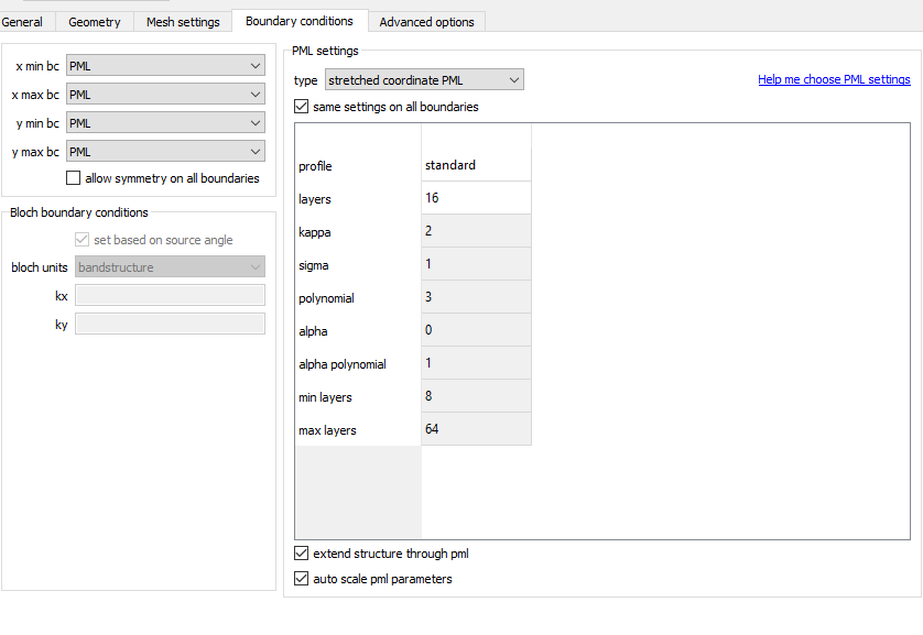
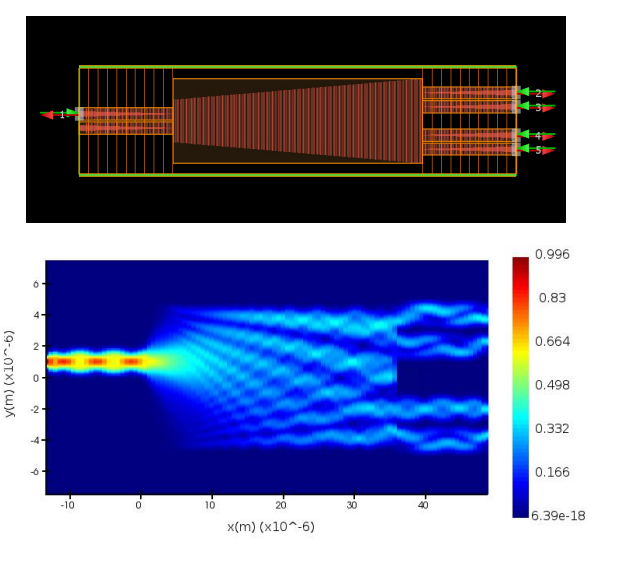
If the device is relatively short and you want broadband result, you can use FDTD. With mode source or port, you should use PML, except the structure has infinite periodicity. In such case you can use "periodic BCs". Bloch BCs are for periodic structure with angled plane wave incidence only.
In most cases EME is better, as it can reuse the periodicity: you only need to draw one period then you can set the number of periods before running "eme propagate".
As I did not see exactly the configuration of your device, those are my suggestions. please try. If you have new questions please write a new post.
Please note, in FDTD, when the periodic type of BC is used, it assumes infinite periodicity; Whereas in EME, except that you set the boundary conditions, the number of periods is alway finite.
-
July 18, 2023 at 10:16 pm
minusunny
SubscriberThank you. Do i need to enable CVCS in EME?Also , do i need to increase the number of cells?
-
July 19, 2023 at 3:49 pm
Guilin Sun
Ansys EmployeeYes you can.
Depending o your machine, you can use more numbers of modes,and you can also use the built-in mode convergence weep.
-
July 20, 2023 at 12:58 am
-
July 20, 2023 at 3:37 pm
Guilin Sun
Ansys EmployeeThe excitation port should be as large as possible to not truncate the source mode;
it seems the PML mightnot be effective as there are interference patterns in the input/output straight waveguides. Please check the PML;
please extend the device outside of the PMLs, but not let them end inside PML;
You may also need to run long simulation time, with smaller autoshutoff min, say 1e-6.
Please add at least one point time monitor at the output waveguides and make sure the signal is completely decayed. You should observe a series of pulses with smaller and smaller amplitude due to the MMI cavity.
This post can be focused on using FDTD.
Â
-
July 27, 2023 at 7:53 pm
-
July 28, 2023 at 7:09 pm
Guilin Sun
Ansys EmployeeThe ripples on the left: it is due to reflection that creates interference patterns.
the cavity: it has standing waves
the right side: it seems either higher order modes are excited, or PML reflection. It might also be due to the iterfence from the leaked beams as the cavity cannot hold all the fields into proper channel.
-
July 28, 2023 at 7:17 pm
minusunny
SubscriberSo, is it a design flaw or a simulation window issue?
-
July 28, 2023 at 10:57 pm
Guilin Sun
Ansys EmployeeNone of them. It is the designed device behavior. You may need to improve the design, and do a convergence test: Convergence testing process for FDTD simulationsÂ
-
August 10, 2023 at 6:36 pm
-
- The topic ‘Subwavelength Grated MMI’ is closed to new replies.
- Import material .txt file with script
- Errors Running Ring Modulator Example on Cluster
- Absorption cross-section of AuNR excited by prism-based TIR
- How to measure transmission coefficients on a given plane .
- TE Polarization Fraction + Waveguide TE/TM Fraction
- Edge Coupler EME Example Issue
- Lumerical Python API Topology Optimization Error 2025 R1
- 2D inverse design grating coupler
- FDE : Simulation waveguides with electrodes
- Loss of lithium niobate phase modulator
-
2262
-
925
-
599
-
591
-
497
© 2025 Copyright ANSYS, Inc. All rights reserved.