TAGGED: #Modal_Analysis, bridge, static-structural
-
-
May 13, 2023 at 3:54 am
Audy Maulizar
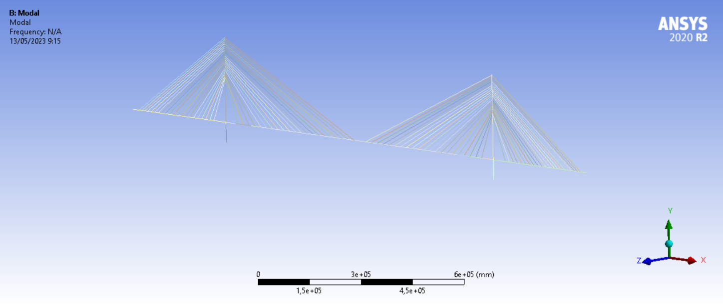
SubscriberI am trying to conduct a static analysis and modal analysis on a simplified cable-stayed structure as shown below. The bridge deck and the two pylons are modeled as beam elements, while the stay cables are modeled as Link element with prestressing which are assigned using APDL commands.
For the static structural analysis, I have tried running the analysis without using large deflection and with large deflection. The analysis ran well without large deflection. However the analysis diverged when ran with large deflection turned on. Trying to run the analysis with large deflection yielded the following error messages.
*** ERROR *** CP = 8.828 TIME= 10:42:04
The value of UX at node 228 is 152664947. It is greater than the
current limit of 1000000 (which can be reset on the NCNV command).
This generally indicates rigid body motion as a result of an
unconstrained model. Verify that your model is properly constrained.
*** ERROR *** CP = 8.828 TIME= 10:42:04
*** MESSAGE CONTINUATION ---- DIAGNOSTIC INFORMATION ***
If one or more parts of the model are held together only by contact
verify that the contact surfaces are closed. You can check contact
status in the SOLUTION module for the converged solutions using
CNCHECK.
*** ERROR *** CP = 8.828 TIME= 10:42:04
*** MESSAGE CONTINUATION ---- DIAGNOSTIC INFORMATION ***
Rigid body motion can also occur when net section yielding has
occurred resulting in large displacements for small increments of load
or when buckling has occurred. You can plot the time history curve
for node 228 in the UX direction to check for stiffness (slope of the
curve) approaching zero.
*** WARNING *** CP = 8.859 TIME= 10:42:04
The unconverged solution (identified as time 1 substep 999999) is
output for analysis debug purposes. Results should not be used for
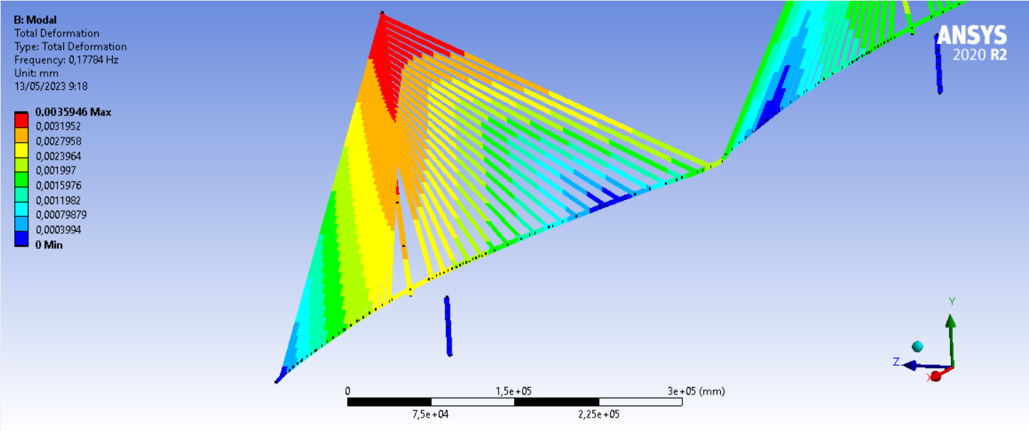
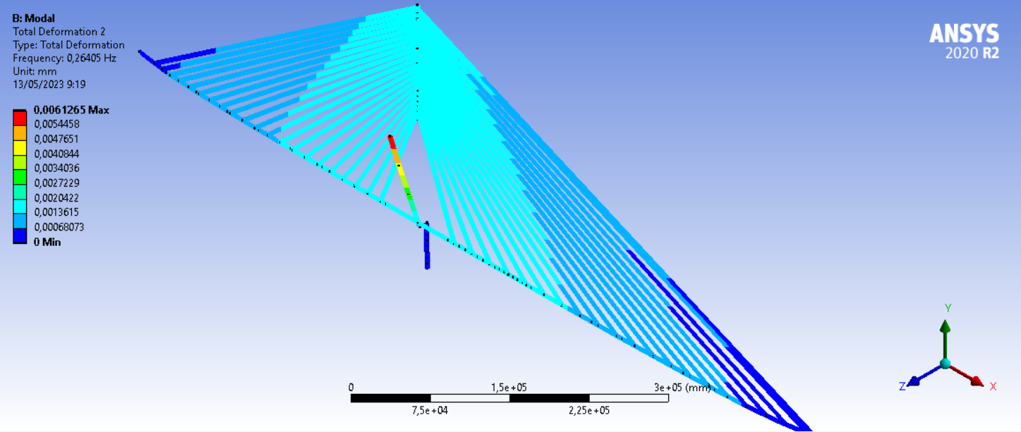
any other purpose.Apart from that, I also have tried doing modal analysis using the results from static analysis without large deflection turned on. The analysis was finished properly, but the some of the resulting mode shapes were abnormal like the ones shown below of which the pylons detached from each other. The program also released a warning message saying that "the model dimensions were determined to be very large".
In short, my goal is to get the static analysis running with large deflection turned on and for the modal analysis to give sensible results. Any help would be greatly appreciated.
-
May 16, 2023 at 6:46 am
Ashish Khemka
Forum ModeratorHi,
Please refer to the following link:
Why does rigid body motion often occur with LINK180 elements? - Ansys Knowledge
Properly constraining the rotation of link elements (may use remote displacement if needed)/ using one element per link should help.
Regards,
Ashish Khemka
-
May 19, 2023 at 3:31 pm
Audy Maulizar
SubscriberThank you Ashish. I already meshed my stay cables so that they are comprised of one element. Regarding the use of Remote Displacement, I am not too sure how to apply it on my stay cables. Do I apply it on the the vertices at the end of the link elements? Or maybe there are other ways to restrain the rotational DOF?
-
-
May 16, 2023 at 11:58 am
peteroznewman
SubscriberIt is clear from the plot that some elements are not connected. Where you see a gap in your plot means that there are two nodes on the ends of two elements. You need to make sure there is only one node used for the end of the element on each side of that node. I see at least two gaps.
-
May 19, 2023 at 3:27 pm
Audy Maulizar
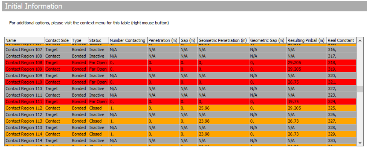
SubscriberThank you for your answer Peter. I'm checking the status of my contact regions using Contact Tool and I found out that some regions are open when they are supposed to be closed.
Any idea what caused this? I used "Create Automatic Connections" to generate the contacts. Should I delete these problematic regions and manually make contacts between them?
-
-
May 19, 2023 at 3:46 pm
peteroznewman
SubscriberThe contacts are Far Open because the Pinball Radius is smaller than the distance between the nodes.
Instead of using contacts to bond elements together, try using Node Merge which will move the nodes to be coincident, then delete one of the nodes after it modified the element to use the other node.
-
May 25, 2023 at 9:09 am
Audy Maulizar
SubscriberHow do you delete the node after merging ? I have tried your suggestion and the analysis gave me an error about an element having zero length.
-
-
May 25, 2023 at 2:09 pm
peteroznewman
SubscriberMerging deletes a node that is within the tolerance of another node. You have to be very careful that there is not an element connecting these two nodes or you will get the error you did. It is only helpful when there is no element between the two nodes.
-
May 30, 2023 at 3:16 am
Audy Maulizar
SubscriberI managed to make the node merge worked by lowering the tolerance value. Now the issue seems to be that the LINK180 elements I use as stay cables are underconstrained when connected to the BEAM188 elements I use as girders. What do I need to do to make sure they are properly constrained?
-
-
May 30, 2023 at 11:57 am
peteroznewman
SubscriberAdd a Sizing mesh control to the stay cable line bodies so there is only 1 element on each stay. Having multiple elements along the stay cable makes the problem more difficult to solve.
-
June 9, 2023 at 8:10 am
Audy Maulizar
SubscriberI already made sure the stay cable elements are comprised of 1 element, but it still gave me errors about solver pivot and to check for insufficiently constrained model. After that, I surpressed the stay cables and tried running the simulation with only the pylon and girder. The simulation ran well even with large deflection turned on. It seems that the problem is on how the stay cables (link elements) are connected to the girders and pylons (beam elements). Somehow, connections between link and beam elements didn't offer enough restraint. I wonder if there's a way to properly connect them?
-
June 12, 2023 at 9:34 am
Audy Maulizar
SubscriberIt works now !
I re-checked the stay-cables' nodes and apparently the node merge feature failed to join them together with the deck's nodes. I solved the problem by re-meshing the deck with smaller element values and tweaking the tolerance value of the node merge. Thanks for your help !
-
-
- The topic ‘Structural Analysis Issues on A Cable-Stayed Bridge’ is closed to new replies.


-
3427
-
1057
-
1051
-
896
-
887

© 2025 Copyright ANSYS, Inc. All rights reserved.


