Ansys Assistant will be unavailable on the Learning Forum starting January 30. An upgraded version is coming soon. We apologize for any inconvenience and appreciate your patience. Stay tuned for updates.
General Mechanical

General Mechanical

Topics related to Mechanical Enterprise, Motion, Additive Print and more.

Stresses at Corners and Edges in Assemblies

    • Frank Astulle
      Subscriber
      Hello Everyone I´ve a doubt about stresses in assemblies. Specially at the corners and edges. For example I´ve done a simple assembly of a plate and a lug. I have defined the same boundary and load conditions for the following cases: 1.-Assembly using bonded contact 2.-Assembly using Share Topology I got the following results, where it is shown that in the corners for both cases there are high efforts, however it seems to me that these efforts are not correct to analyze whether the element fails or not. So I get the following questions: 1.- Why are the efforts concentrated in the corners? 2.- Is there a way to eliminate these stresses, without modeling the weld? Because since this is the maximum point, the color scale identifies this value and can give a perception that some point of this design is failing. I raise this because when you have too large assemblies, it is not efficient to model all the welds either. 3.- And in the case that welding is modeled, it would give me the perception that modeling a larger fillet would lead to having less stress in said area. Is this correct? 4.- Let's imagine that this part is made of a single element (machined), without welding (or perhaps with a fillet that is too small). So, in this case it would not be necessary to model the weld, so when obtaining a stress greater than the yield stress in this area, will the part fail in that corner? Greetings
    • Akshay Maniyar
      Ansys Employee

      Hi Frank,

      Can you please check the below video from Ansys innovation courses?

      Understanding and Dealing with Artificially High Stresses — Lesson 3 - ANSYS Innovation Courses


      Thanks,

      Akshay Maniyar

    • Frank Astulle
      Subscriber

      Thanks, so I should model the fillet of welding to verificate that the stress in the corner is below the yield strength. But for large assemblies with a lot of contacts and singularities, to model welding would take a lot of time.

      In my opinion, in the case I present, having a value of 350 MPa in a very small concentrated area, I could disregard it, but what would happen if instead of 350 MPa it had 1000 MPa, would it still be disregarde?

      Is there any other way to recognise that these stresses are within the elastic limit without making welding model recommendations or guidelines?
      If I want to know the factor of safety of this element, what stress should I assume as the maximum?, How far from the corner where the artificial stress exists?


    • peteroznewman
      Subscriber

      Frank,

      To model all the welds in a large assembly would take a lot of time. One approach to reduce the modeling time is to divide the analysis into a System model and one or more Detailed models. In the System model, you don’t need to model the welds, instead you insert a Joint between the hole in the lug and the strut connected to the lug for the purpose of extracting the forces and moments going into the lug. This is done for every lug in the System model. Probe the forces and moments of each joint and put the results into a spreadsheet. If the lugs are not all the same shape (and size), create a label for each unique shape and add a column in the spreadsheet to label each row with the lug shape. Sort the rows by lug labels and then by forces to find the largest force for each lug label.

      Make a Detailed model for each unique lug shape. Apply the largest row of forces and moments for that lug shape to the Detailed model of that lug shape to evaluate whether it has positive stress margins for the largest forces and moments going into that lug shape. Repeat for each lug shape.

      The benefit of this approach is you can use a coarse mesh on lugs without fillets in the System model because you are not looking at stress in the System model while the Detailed model uses a fine mesh on one lug with fillets to evaluate the stress.

    • Frank Astulle
      Subscriber

      Peter

      I think you refer to use a body-ground joint in each lug. So for this case Should I use the following type of joint?

      System model is just a general model whitout fillets, and detailed models area specfic models of each type of lug with fillets. Is this correct?

      What about consider a plastic limit strain? Fox example it could be consider establich a limit of 5% to the limit plastic strain. So Should I check Equivalent Plastic Strain or Equivalent Total Strain, which one? And then ensure that this is less than 5% or 0.05. Could it be reasonable?


    • peteroznewman
      Subscriber

      Frank,

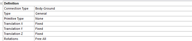
      Use a Body-Body General Joint in the System model.  One end is scoped to the hole in the lug, the other end is scoped to the feature that has a pin through that lug hole. To represent the pin without modeling the pin in the System model, leave the Joint rotational DOF parallel to the pin Free. Since the System model has many lugs of the same shape, but oriented in many different directions, create a local coordinate system at each lug. Align the local X axis to the normal of the base and the the local Z axis normal to the face of the lug. Use each local coodinate system to define the Joint Csys and for force output from the joint. In that way, sorting the forces in the X, Y and Z direction means you can apply the maximum force in the correct directions to the Detailed model.

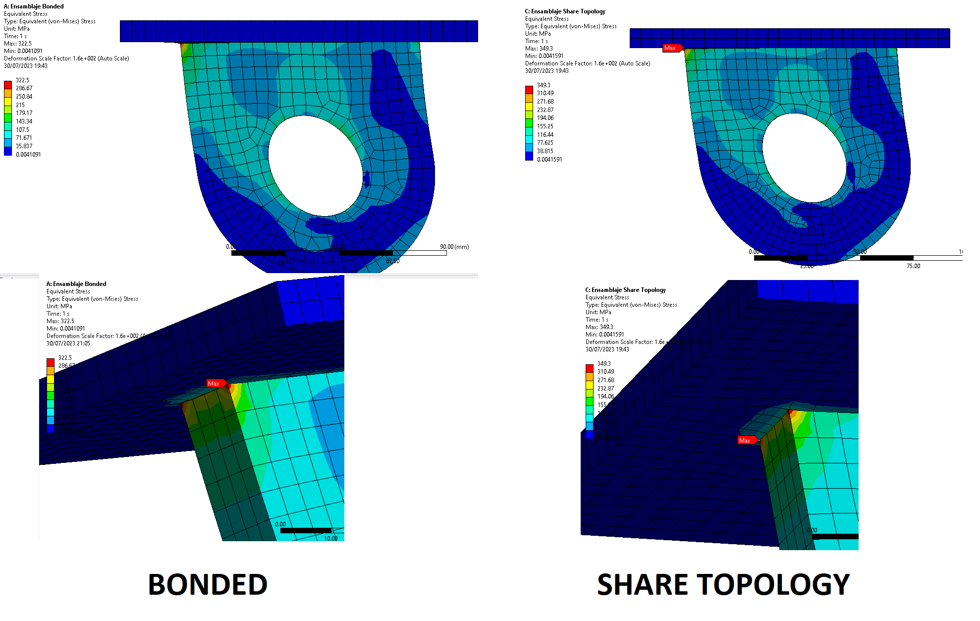
      I assume the structure sees cyclic loading, which means the materials are subject to fatigue failure. Fatigue failure is dependent on the stress amplitude and the number of cycles. The stress amplitude depends on the radius of the fillet at the interior corners. A lug machined out of a solid block of material has uniform material properties so you can use the stress on the face of the fillet to evaluate the cycles to failure for that material.

      A lug welded to a base plate does not have uniform material properties. Weld material is full of tiny cracks so its fatigue strength is much lower than the parent metal it connects. Look up a weld design standard for your country to learn how to design a welded joint.

      Weld beads are often left as welded, which creates geometry with many stress risers where the angle changes suddenly from the weld face to the plate face it is joined to. To eliminate the stress risers, the weld bead has to be ground down to create the fillet radius.

      Total plastic strain is used evaluate the elongation at break for a ductile material under a single load to failure. But if you have to design for fatigue of a welded joint, you will find you need to design for a lower stress than the yield strength of the parent metal.

Viewing 5 reply threads
  • The topic ‘Stresses at Corners and Edges in Assemblies’ is closed to new replies.
[bingo_chatbox]