TAGGED: transient-structural
-
-
September 7, 2024 at 7:50 am
nm0770
SubscriberI would like to perform a transient simulation of carbon fiber components. The two sandwich plates with attached stiffening Rips are connected using bonded MPC contacts.
The boundary conditions are as follows: on the front side, a remote displacement is fully constrained in all directions and on the rear side, it is constrained in such a way that expansion in the length direction is still possible.The plates rest on 8 points on the ground.
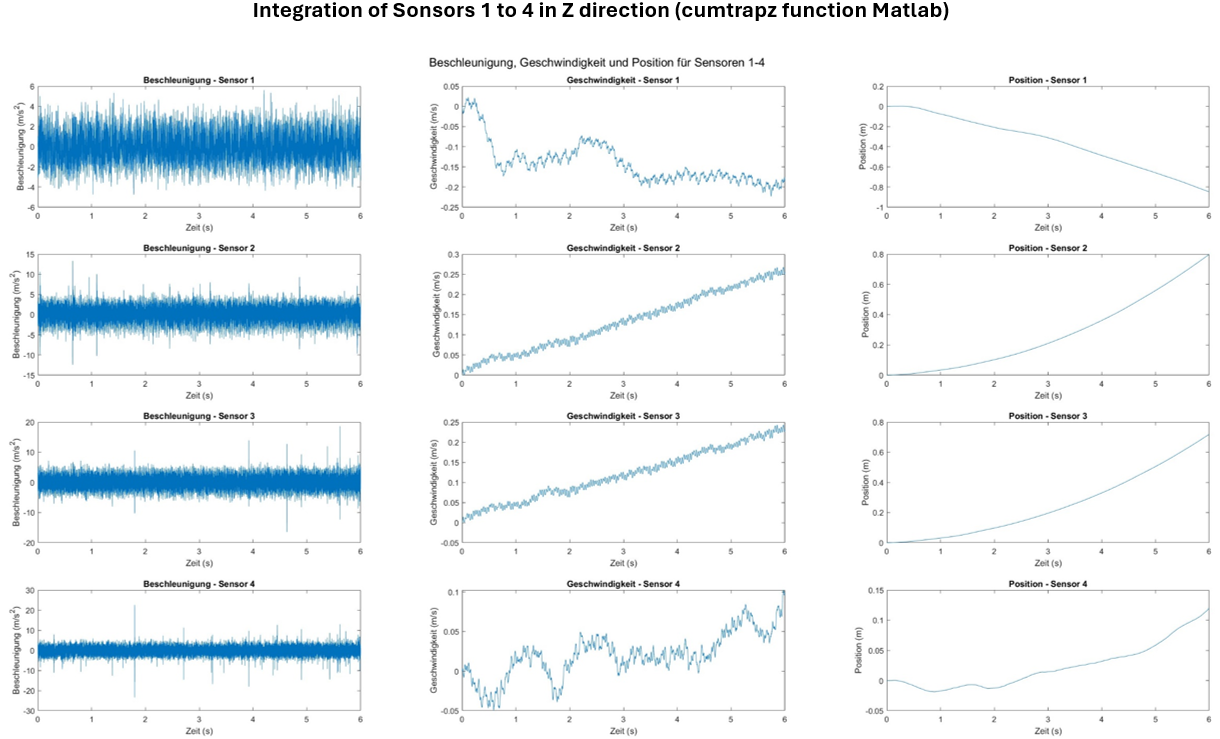
These points are constrained in the Z direction using remote boundary conditions. (Also tried with fixed fixed configuration same result.)I applied measured accelerations to each of the 8 boundary conditions on the ground (6000 steps measured at 10 000 Hz -> as I understand, this results in a time step of 1/10 000 (Mesurement Time was 0.6 seconds)).
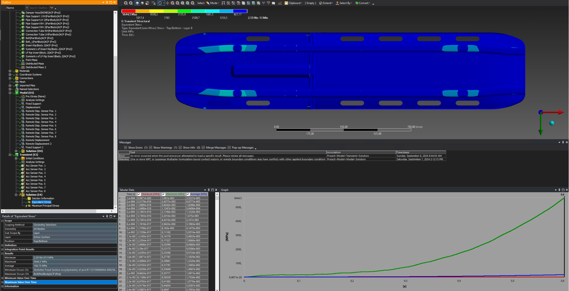
The mesh used has already been applied in static simulations and has converged in those cases.I am outputting the equivalent stresses and obtaining a maximum of approximately 6000 MPa, which I consider unrealistic.
The maximum stresses occur in the area of the support points on the ground.
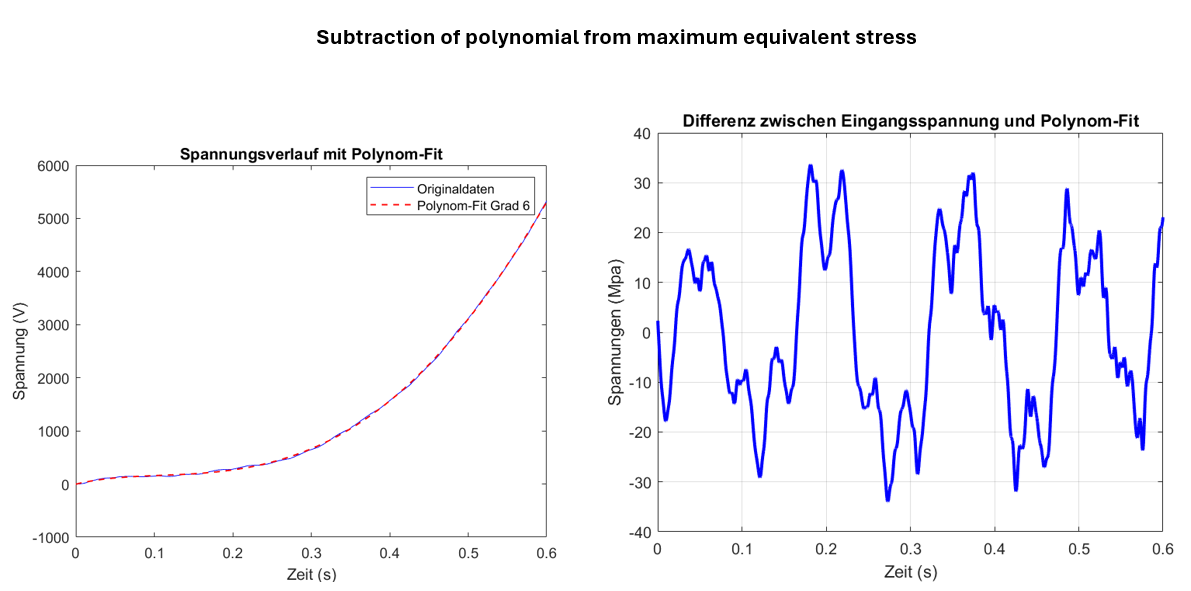
My main idea is to perform a static analysis that includes gravitational acceleration, followed by a indeoendent transient simulation.
I would then sum the maximum stresses from both analyses (at a critical Element of the geometry). If the sum of these stresses is below the fatigue limit (~450 MPa), can I assume that the structure is durable and will not experience fatigue failure? Is this approach valid for a preliminary assesment, or are there other factors I should consider?Can anyone provide me with tips on how to proceed, or possible Problems?
-
September 9, 2024 at 1:51 pm
danielshaw
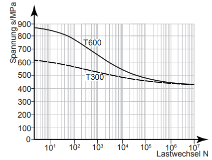
Ansys EmployeeIf you are sure that the alternating stress is below the endurance limit, you can assume infinite life. Based on the S-N curve that you showed, this material appears to have a well-defined endurance limit at about 450 MPa, but in general
- Not all materials have a well-defined endurance limit. So, if the part experiences very high cycle fatigue, you may not be able to assume infinite life,
- 450 MPa seems like a relatively high endurance limit.
-
September 9, 2024 at 2:41 pm
dlooman
Ansys EmployeeThe gravity step can be solved with time-integration off in the Analysis Settings details to avoid any dynamic effect from gravity.
-
September 9, 2024 at 2:41 pm
dlooman
Ansys EmployeeThe gravity step can be solved with time-integration off in the Analysis Settings details to avoid any dynamic effect from gravity.
-
September 9, 2024 at 3:21 pm
nm0770
Subscriber
-
- You must be logged in to reply to this topic.


- LPBF Simulation of dissimilar materials in ANSYS mechanical (Thermal Transient)
- Real Life Example of a non-symmetric eigenvalue problem
- How can the results of Pressures and Motions for all elements be obtained?
- BackGround Color
- Contact stiffness too big
- Element Birth and Death
- Python-Script to Export all Children of a Solution Tree
- Which equations and in what form are valid for defining excitations?

-
4597
-
1495
-
1386
-
1209
-
1021

© 2025 Copyright ANSYS, Inc. All rights reserved.


