-
-
December 26, 2019 at 8:30 am
lincs2k9
SubscriberI have some confusion about the stress result of this below analysis. Need clarification-
Fixed support has been mentioned in the below image. A force has been applied in the negative Z-direction as in the below image.
Now, what is the meaning of these negative and positive stress result of SX, SY, and SZ showing in the below images-
Another issue is which stress result indicates the tensile stress in the negative and positive Y direction or from which option I can find that result.
Your valuable reply can help me to clear my confusion.
-
December 26, 2019 at 2:05 pm
peteroznewman
SubscriberIn the midpoint of your column, you have fairly uniform stress of about -30 MPa. That means a compressive stress.
At one end of your model, you are seeing artifacts from the fixed support not allowing the sideways expansion of the material caused by Poisson's ratio.
At the other end of your model you are seeing artifacts from applying the force to a node instead of the whole face.
Attached is a model of a column that has a perfectly uniform stress. That is because it used 2 planes of symmetry and a Z = 0 Displacement constraint to avoid the artifact at the fixed support end, and it applied the force to the face, not a node.
-
December 26, 2019 at 2:30 pm
lincs2k9
SubscriberHello Peter,
Thank you for your reply. Actually the rectangular block is an adhesive block and a wire inside the block. Due to material properties of wire, if I increase temperature whole the body uniformly then the wire will be compressed in negative z direction according to image which creates compressive stress on adhesive block. Actually I want to know what is the tensile stress created in negative and positive Y direction according to my model orientation.
Should I use displacement constraints instead of fixed support? Â
So, according to my image, those negative stress shows compressive stress and positive stress shows tensile stress in SX, SY, and SZ?
-
December 26, 2019 at 4:30 pm
peteroznewman
Subscriber
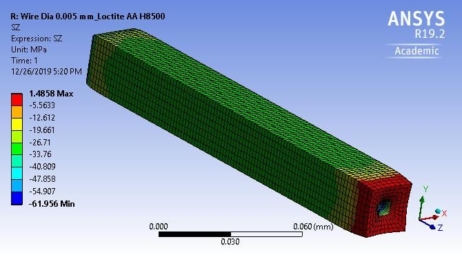
I understand now. The CTE of the adhesive is much higher than the CTE of the wire so when the temperature increases, the adhesive develops a compressive stress, while the wire develops a tensile stress.
You will have an end effect at each cut end, but you can clearly see what is going on at the midpoint of your model by slicing on the XZ and YZ planes through the center of the wire, and making the XY plane have the Z = 0 constraint. That makes the XY plane equivalent to the midpoint and just like a third plane of symmetry. Then you can clearly see what is going on through the thickness of the adhesive.
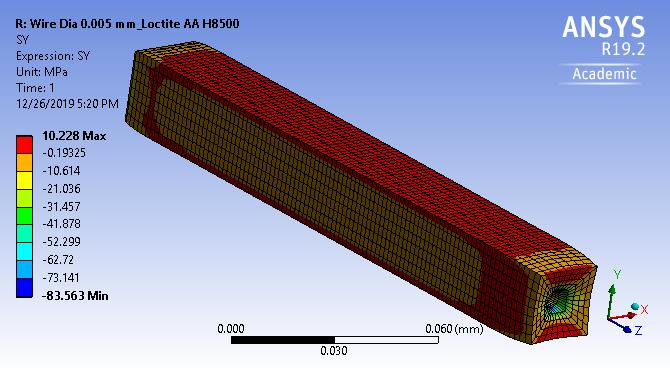
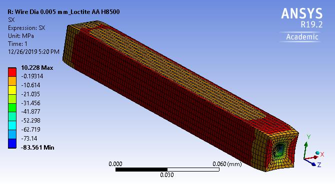
A free surface with no pressure load has zero normal stress, so the SX and SY stresses are zero at the outer surface of the adhesive when you look at it near the XY plane, away from the end where the wire is pulling the face inwards.
-
- The topic ‘Stress result analysis in Static structural’ is closed to new replies.
-
6029
-
1906
-
1425
-
1308
-
1021
© 2026 Copyright ANSYS, Inc. All rights reserved.


