General Mechanical

General Mechanical

Topics related to Mechanical Enterprise, Motion, Additive Print and more.

Static equilibrium of rigid body system.

    • alpivanvik
      Subscriber

      Hello!

      I have a question about Rigid Dynamics and Static Structural. Is it possible to find static equlibrium of system of rigid bodies using these types of analysis? In more detail, I want to model a system of rigid rods connected by springs. There is also a load applied to the end of one of the rods. The load is constant and shouldn't change direction. The problem is to find a static equilibrium of this system under the load. Masses , materials and radii of rods don't matter because the problem is static.

      I tried to do that with 1 horizontal rod (modeled just by solid cylinder) connected to the ground in one of its lateral faces by revolute joint with non-zero rotational stiffness. I tried to apply load to the other lateral face of the cylinder.

      First I've tried Rigid Dynamics analysis but I faced the problem that only Remote Force can be applied to the rod. But I don't know is it ok to define the origin of remote force to be not on the face I want to apply this force to. I tried several times to apply the force from different locations. The solution always failed. Anyway, I don't really know if it is possible to solve static problem in Rigid Dynamics where it's not possible to make a constraint of zero acceleration for example.

      In Static Structural I've also defined Remote Force because the solver said that usual Force can't be applied to rigid body. Solution didn't converge, it has many errors, including "Not enough constraints appear to be applied to prevent rigid body motion." That's why I don't know is it possible to to solve static equilibrium problem of rigid body in Structural as it's always trying to prevent rigid body motion.

      It would be very nice to get an answer for my question. Thank you very much!!!

    • peteroznewman
      Subscriber
      Use Static Structural to find the static equilibrium of a system of springs and rigid bodies. It will be easier to help if you insert an image into your reply.
      You need a minimum of 6 springs connected to ground so that all 6 Degrees of Freedom (DOF) of the structure has a non-zero stiffness in each DOF. Also, there can be no mechanism in the structure.

    • alpivanvik
      Subscriber
      Thanks @peteroznewman for your answer! Here I apply the photo of the system I want to model. Briefly, there're 3 rods (on the right side of the picture) that have a spherical joint with the ground. All the other joints between rods should be also spherical with non-zero stiffnesses (that's what I meant when I wrote about springs) . I actually haven't quite understand your note about 6 springs. Could you please explain it more? Is the structure on the picture appropriate for Static Structural?
      There is also a problem here with the spherical joints. I read about this type of joint and how the friction moment is calculated based on radius, friction coefficient and surfaces of the joint. I didn't understand is it valid to define the joint between the ground and the top face of the cylinder as is shown on the 2nd picture (and also if I want to create a joint between 2 consecutive rods, I would need to define a joint between the bottom of one cylinder and the top of another). The problem here is that here the center of the joint is located in the center of the face and the radius of the joint is 0, so, as I understand, the moment would be 0. All I want is just to make some kind of connection between rods that would produce a counteracting moment that is proportional to change of angles in this joint. (like in a revolute joint, where we have M = c*phi, but here in spherical joint we have 2 angles, as I don't want to account intrinsic rotation of cylinder around its axis). Maybe I just need some other type of joint for this purpose?
      Thank you in advance!
    • peteroznewman
      Subscriber
      I see you have 12 rods that you want to connect with a spherical joint and a spring that creates a restoring moment proportional to the angle change. This can be achieved by using a COMBI250 element.
      Open ANSYS Help and paste the following into the Browser window.
      https://ansyshelp.ansys.com/account/secured?returnurl=/Views/Secured/corp/v221/en/ans_elem/Hlp_E_COMBI250.html
      This element defines 6 spring constants between two nodes. Three translational spring constants and three rotational spring constants. By using large values for the translational spring constants, such as 10^8 N/m and small values for the rotational constants, you will effectively have created a spherical joint that has a restoring moment to return the rods to their initial angles.
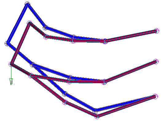
      Open SpaceClaim and create 12 new Components. Draw one rod in each Component as a line body. Separate components assures that when two rods meet at a common point, they each get a node on the end and don't share a node as that would weld the rods together into a single structure. Create an extra Component call it Ground that has three nodes to connect with a node on one end of rods 1, 9 and 12. You can draw the triangle defined by the three ground points. For the rods, if it is easier to draw solids than lines, you can do that and use the Prepare tab to convert the solids to Beam elements.
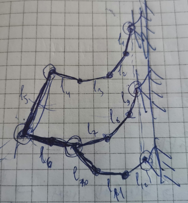
      Make an exploded view sketch with shortened rods so that there is a gap between the ends of the rods to leave room to draw a short COMBI250 element. Number all the nodes and elements (Ground nodes, Rod nodes and elements and COMBI250 elements).
      To make the connection where three rods: 6, 7 and 10 come together, there will be two COMBI250 elements, one connecting 6 and 7 and another connecting 6 and 10.
      In future posts, it is better to insert the image into the post using the Image button, rather than attaching a file because ANSYS employees are not allowed to download attachments.
    • alpivanvik
      Subscriber
      Thanks for your answer! I created line bodies in SpaceClaim in new components. I just didn't fully understand where I can define small beams as COMBI elements. Do I understand correctly that I can do that only by inserting APDL commands in Mechanical?
      And here another question arised. I've read in Help that Bushing joint uses COMBI elements inside so I've tried to import just 12 beams into Mechanical as stiff beams. Then I've defined body-body Bushing joints between the beams and body-ground Bushing joints between 1, 9, 12 beams and the ground. But then I got error message that Static Structural analysis doesn't support joints with bushing formulation.
      Then I've tried to change the formulation of the joints to MPC and I got a pack of errors shown on the picture below:
      Does that mean that I can't model the problem with joints and that I need to use COMBI elements directly? And I don't know will there be a problem of preventing rigid body motion if I will use COMBI elements.
      Could you please answer these questions too?
      Thank you in advance!


    • peteroznewman
      Subscriber
      Yes, you have to use APDL commands to create the COMBI elements in the model. If you use COMBI elements, you don't need joints to connect two links.
      Bushing is a connection to ground. You want a connection between two links, so you don't want to use a Bushing.
      It will be helpful if you make a sketch of all nodes, links and COMBI elements and label everything with numbers.

    • alpivanvik
      Subscriber
      Hello, sir!
      I did what you said to do in SpaceClaim: created beams, made an exploded view and created small beams that will stand for COMBI elements. But when I import this geometry to Mechanical, it doesn't correspond to the geometry from SpaceClaim. Specifically, small beams are not in their places and there're no gaps between main beams. Could you please look at my workbench file that I uploaded here? I don't understand why Mechanical would not import geometry correctly.
      Thank you in advance!
    • peteroznewman
      Subscriber
      I know how to make your model in NASTRAN. The image below shows the links connected with springs, with a downward load shown with the green arrow. After the static equilibrium is solved, the links are deflected downward.
      I exported ANSYS commands for this model in the attached text file.
      If you start Mechanical APDL, and read in this file, you will have the solved model, but not in Workbench. I'm not an expert at Mechanical APDL, but I can see the deformed shape! When plotting deformation results, there is the real deformation, which might be small, then there is a viewing scale factor, which can make the deformation look larger than it really is, but makes it easier to see how it is deforming. The plot above has a larger viewing scale factor.
      Good luck!
    • alpivanvik
      Subscriber
      Thanks for your reply! Do you mean Siemens NX Nastran or MSC Nastran ? And is the txt file that you applied generated automatically from Nastran? Because it seems that it's really hard to write all these commands by hand. Also, if you don't mind could you please upload Nastran model shown on the picture from the above comment?
    • peteroznewman
      Subscriber
      The NASTRAN text file will run in either NX Nastran or MSC Nastran.
      Change the extension from .txt to .dat if you want to run it in a Nastran solver.
    • alpivanvik
      Subscriber
      Thanks for your reply!
      I've tried to solve smaller problem in Ansys as Static Structural. I created 2 beams in SpaceClaim as separate components. Then I added Bushing joint between the ground and the first beam and created a spring between the beams that I then changed via APDL commands to be COMBI250 element as you suggested on this forum earlier. I applied a force to the end of the 2nd beam. There is also a thing that I don't understand: when force is applied by components it's written that it is ramped and I don't understand why it should be ramped and how to make it just constant. Nevertheless, solution didn't converge on a whole time period and the behaviour of the beams (deformation) obtained from solution is very strange.
      On the above picture the total deformation and the direction of applied force is shown. As I said, from a common sense such behaviour of the beams is strange. Maybe you will have an idea what is going wrong with this model?
    • alpivanvik
      Subscriber
      I'm sorry, I forgot to apply the model for the previous comment.
    • peteroznewman
      Subscriber
      I remeshed with 3 linear elements and set many substeps in the Step Controls.
    • peteroznewman
      Subscriber
      I think you can have a zero length COMBI250 element. The two nodes at the end of each link can have the same exact coordinates. This may be a cleaner model for you.
    • alpivanvik
      Subscriber
      Thank you very much! Though the result of the total deformation of the system in your file is inconsistent with theoretical results.
      I've tried to make zero length COMBI elements by transforming beam or spring connections to COMBI by APDL. This approach doesn't work because Ansys doesn't support zero-length springs and beams. So I've tried to make a bushing joint between the beams with bushing formulation and then insert APDL commands same as for the spring. I've also kept the number of elements and increased the number of substeps and this approach actually worked and it's consistent with theoretical results!
      So, again, thank you very much for your help! I'll try to do the same thing for the initial problem!
    • alpivanvik
      Subscriber
      Hi, Peter!
      I've been wondering if it's possible to model at least my 2-beam model with universal joints instead of bushing joints as in theory when I have 2 connected beams I need to omit the angle of intrinsic rotation and that's why in theory I have only 2 DOFs in the joint between 2 beams. So I've tried to build a model using universal joint and I have a few questions. First of all, is there no option to define stiffness for this joint via Mechanical GUI, is it possible to do only by APDL commands? And also I read in APDL element reference that "the specification of the second local coordinate system at node J is optional.", while there's also no option for specifying 2nd coordinate system for universal joint via GUI. Is it also posiible to specify it only by APDL?
      I've inserted APDL commands for both joints. For the joint between the beams I've used TB and TBDATA for specifying stiffnesses and SECJOINT for specifying local coordinate systems. The mesh, the load and the analysis settings I entered similar to what they were in earlier models. The problem is that Mechanical just stuck on building mechanical model and doesn't provide solution. Could you please kindly look at my model that I apply below?

Viewing 15 reply threads
  • The topic ‘Static equilibrium of rigid body system.’ is closed to new replies.