TAGGED: gear
-
-
September 1, 2022 at 6:43 pm
-
September 2, 2022 at 7:23 am
Florian.CHANCEL
SubscriberHello,
I have done this type of calculation before, with simple gear or planetary gear.
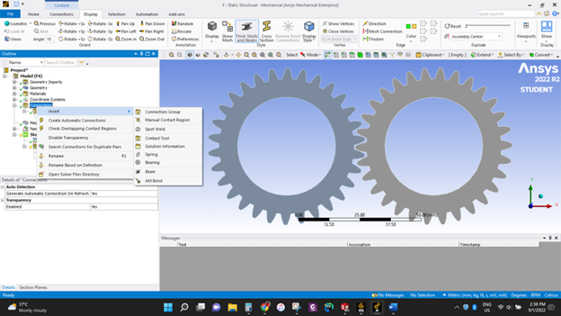
If you just want a simple rotation, you can add a remote displacement in the boundary conditions, and release the rotation DOF.
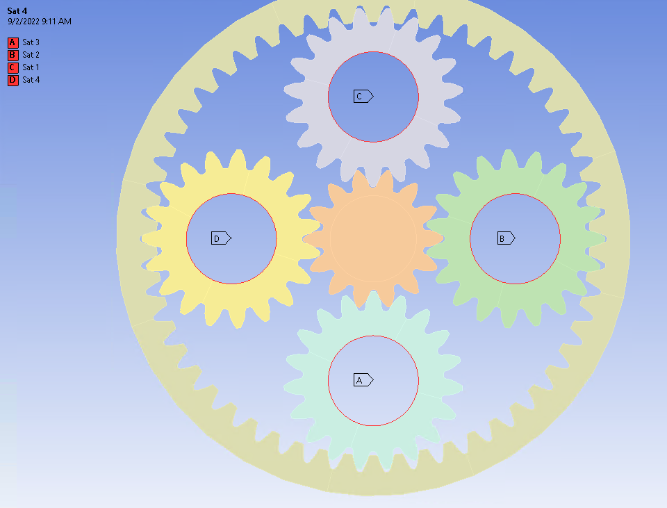
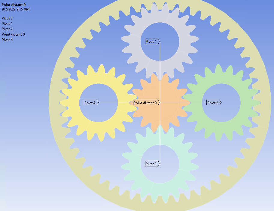
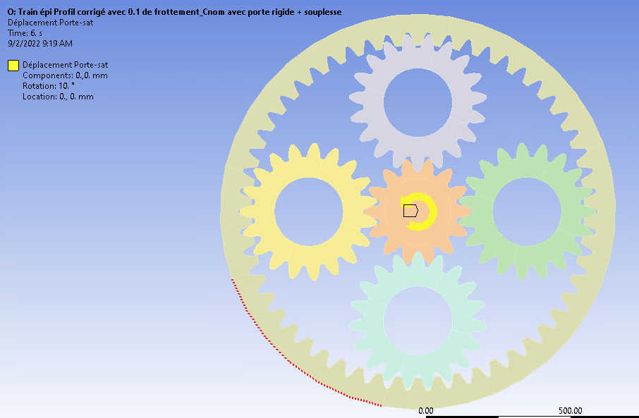
If you want a coupled rotation for instance like the satellite displacement, it's more complexe :Firstly, I defined Remote points of the satellite's center
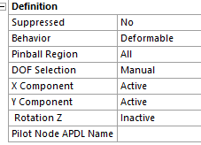
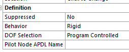
And I defined their DOF
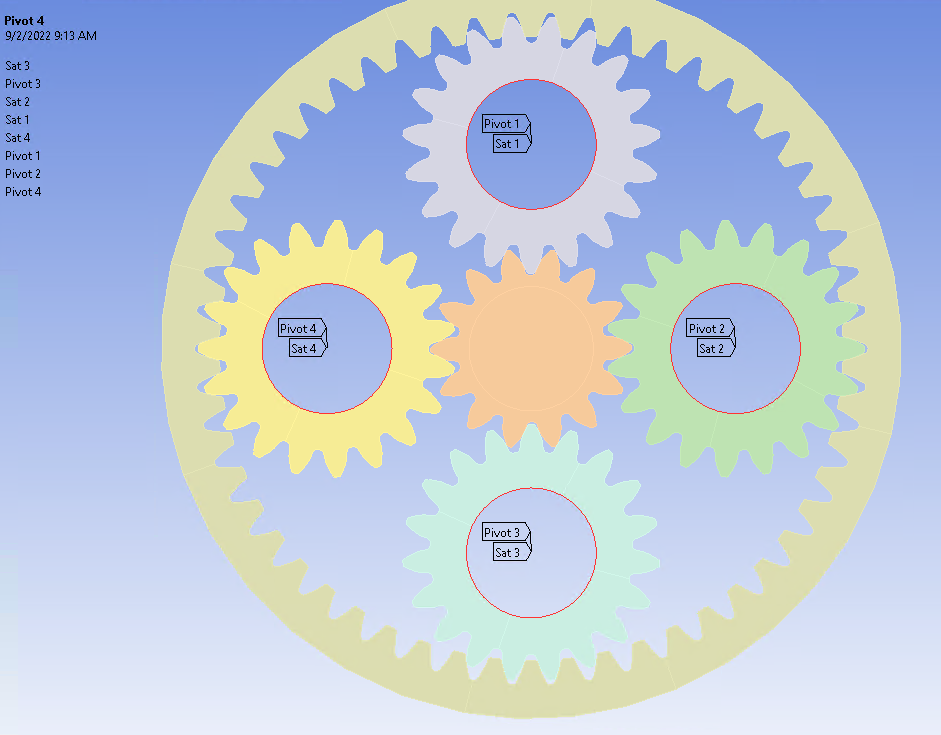
Secondly, I defined a "bearing remote point" of the remote point created before
And I defined their DOF
In a third step, I defined a distant point corresponding to the center of rotation of the planet holder
And I defined its DOF
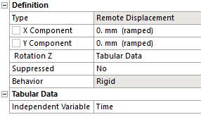
And finaly, I defined a remote displacement of this last remote point, in the boundary conditions
To controle the rotation DOF
Maybe, this process could have been less complex.
I hope this will help you,
Regards,
Florian C.
-
September 6, 2022 at 1:10 pm
fab88
SubscriberThank you for Florian,
I'm working on a simple rotation.
I'm going to try as you suggested.
I will come back with my results.
Thank you again.
-
September 16, 2022 at 5:36 pm
fab88
SubscriberHello, Florian!
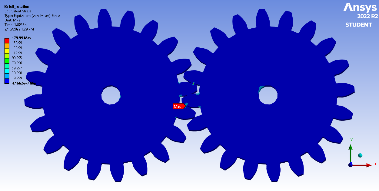
I have managed to successfully run the 2D model.
Thank you for your guidance.
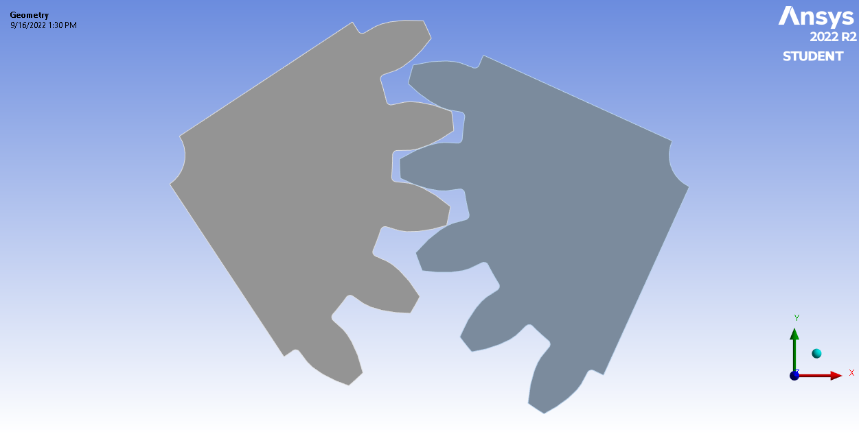
Now, I am trying to reduce the computation time and improve the accuracy by using a simulating frictional model of the gear instead of the full gear.
However, it seems my boundary conditions are giving me trouble.
Do you have any guidance on how I should proceed?
I am attaching a link to my archive file (https://drive.google.com/file/d/1onwLXCv5wEWG3J-OHG6lB1HRL5rP8Sm_/view?usp=sharing ) for your review.
Thank you
-
September 19, 2022 at 11:25 am
Florian.CHANCEL
SubscriberI cannot open you project.
I think you sent me the wrong file. It's not the archive file.
Can you try again ?The frictional contact between your teeth must have a "close statut" at the beginning of the calculation otherwise it will not converge.
I don't see your mesh, but you can compute an inflation to have accurate results.
-
September 19, 2022 at 6:50 pm
fab88
SubscriberSorry,
I come to realize that I attached the wrong file.
The initial contact status is closed.
Here is the correct file.
Thank you.
-
September 20, 2022 at 6:01 am
Florian.CHANCEL
SubscriberI cannot open your file because it's an older version than I have(I use 2021R1).
Can-you try to explain your boundary conditions, your load cases, your mesh and connexion details ? -
September 21, 2022 at 7:53 pm
fab88
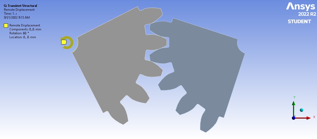
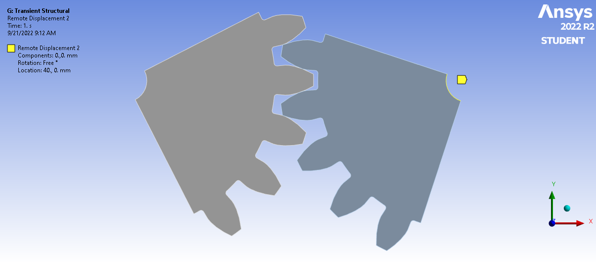
SubscriberActually, I had forgotten to apply a remote displacement on the driven gear. But now, it is working.
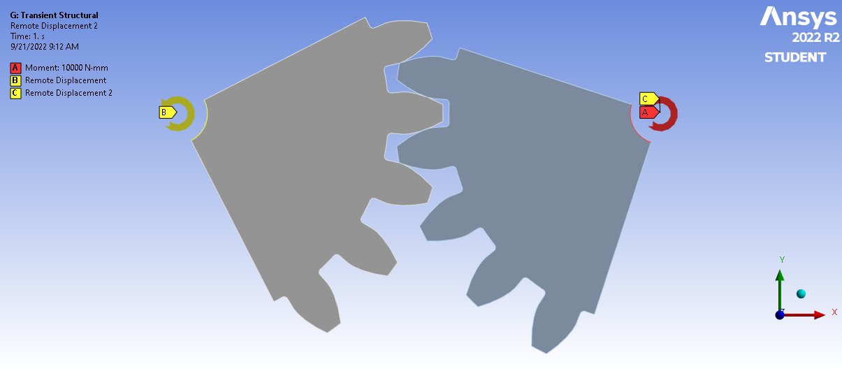
Here are my BCs.
Also, I had to include in weak springs to avoid rigid body motion.
Now, I am facing another problem. When I am trying to allow full rotation (360) of the cut gears, the solution fails to solve. Let's say, I want 10 revolutions.
I mean after this time.
What can I do?
Thanks.
-
September 22, 2022 at 6:10 am
Florian.CHANCEL
SubscriberOk, you have to set up some steps to help the static calculation
Step 1 : You lock (0°) the rotation of the left pinion, and apply the torque on the right pinion.Step 2 : you rotate the left pinion (for example 10°) => In this step, you have to set up sub step every 1°(or more) => Substeps are the key to the convergence. Your calculation have to stay in static, if the rotation gap is to big, calculation will fail
Advice 1 : You should fixe your remote point on the two cut edges of your pinion and set up the rigid behavior
Advice 2 : turn on "large displacement"
Advice 3 : Weak springs are not a problem, you just have to check if the reaction forces are near 0 N after your calculation.
Advice 4 : 360° is not useful, I think juste a rotation on 3 teeth are good enough to capture all results.
Can you show your mesh, can you send me CAD file in .step ?
Can you show me the parameters of your frictionnal contact ?
-
September 22, 2022 at 6:15 am
Florian.CHANCEL
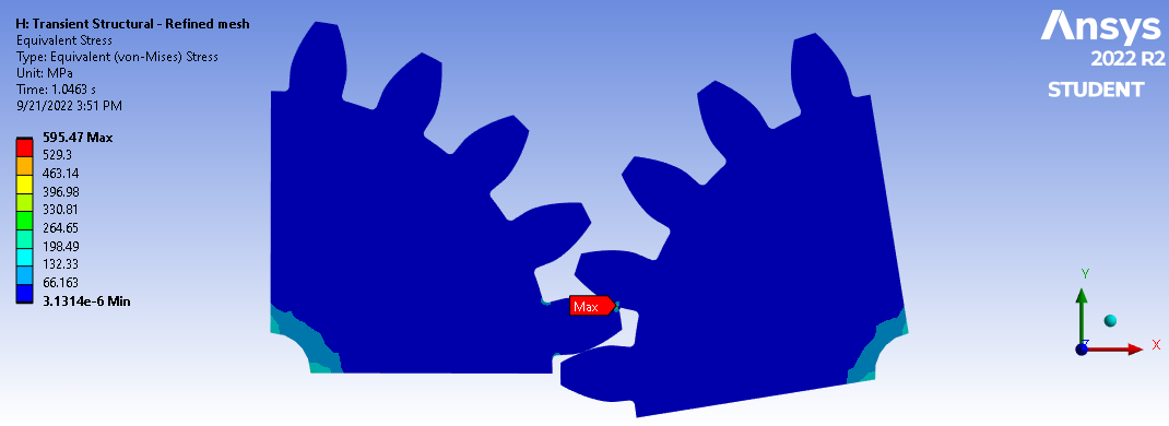
SubscriberOk, I also understood something thanks to your pictures.
The rotation of your left pinion is counterclockwise => Therefore, after 1.0463 sec, as you can see, you have the last contact point on the last teeth. So there is no anymore teeth to keep the input torque ! I think your calculation fail because of this.
ou cannot have 360° or 10 revolutions because you have only 1/4 of your pinion.
-
September 22, 2022 at 2:23 pm
fab88
SubscriberThe project that I am working on consists of calculating displacements/ stresses and temperatures. It is a transient thermomechanical analysis. Therefore, I need to have more revolutions to get to a stable temperature. Young's modulus is a function of temperature. In order to reduce the computation time, I cut the gears into quarters.
The calculations I was doing are preliminary (Transient structural analysis)
The torque on the left gear (driven gear) is an output torque.
The remote displacement on the pinion is equivalent to a constant angular velocity.
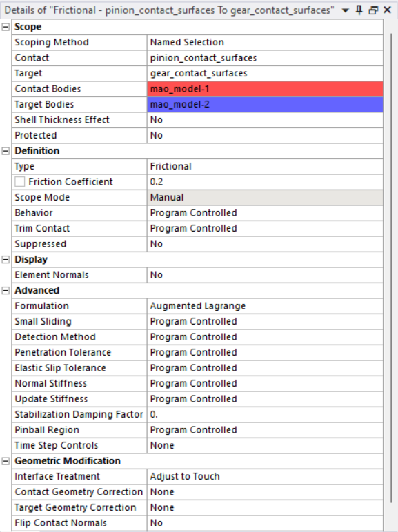
Here are my frictional contact details
Here is my CAD file.
Thank you again.
-
September 27, 2022 at 3:51 pm
fab88
SubscriberHello Florian,
I'm still stuck.
Have you found a way to have a full revolution?
Thank you.
-
September 28, 2022 at 5:28 am
Florian.CHANCEL
SubscriberHello Fab,
I don't really understand what you want. If you need a complete revolute of your pinions, you have to represent the complete pinions, and not a quarter, right ?
If you import your transient thermal calculation, maybe you can split the input time in different static calculation ? in this way, you may cover temperature with different 1/4 of model ?
-
September 28, 2022 at 1:24 pm
fab88
SubscriberI am going to do full gears and a coarse mesh to the region of less interest.
Thank you again.
-
- The topic ‘Spur gear stress analysis’ is closed to new replies.


-
3472
-
1057
-
1051
-
934
-
902

© 2025 Copyright ANSYS, Inc. All rights reserved.

