-
-
May 14, 2018 at 11:53 am
-
May 14, 2018 at 12:17 pm
-
May 14, 2018 at 2:59 pm
KeevKK
SubscriberThank you. I had already read that post and have done some work which I am doubting. For your information, I am not really qualified to do this kind of analysis, and my professors are not able to help me either since they are not competent enough (according to them).
This model is imported from Inventor as a step file and is created by the involute curve. Is there anything else you want/need to know?
So these are my contacts which I am unsure about:
But what contact type should be used? Anything else?
This is how I have put my boundaries and moment:
Is this correct?
Thanks a lot.
KeevKK
-
May 15, 2018 at 2:28 am
peteroznewman
SubscriberI assume you want to calculate stress in the tooth, but I don't see any root fillet. This is an essential feature of a real manufactured gear, but is not created by the CAD system that creates "gear teeth", which are not usually real involute tooth profiles and lack many features of a real gear tooth profile such as a root fillet.
Once your geometry adds a root fillet, your model is under constrained with the frictionless support. There is nothing to stop the gear from slipping axially along the support. That is why a revolute joint is better. The moment can be applied as a joint load.
As I mentioned in the other discussion, you can get a lot better model if you do a 2D plane strain model in the X-Y plane.
-
May 15, 2018 at 6:53 am
KeevKK
SubscriberI have actually not used the gear tool in CAD, but used the function of the involute curve, if that makes sense. I just forgot to add the fillet radius which was a mistake.
Can you tell me more about the revolute joint?
Also how would I go about making my a model in a 2D plane. I could not assemble the 2 gears.
-
May 15, 2018 at 10:05 am
KeevKK
SubscriberOk so I managed to make this new pinion (with fillet) and do a simple analysis:
What I cant figure out is how I use a single pinion with a gear instead. I do not know how to replace the upper pinion with my original gear.
How do I go about that?
I have already created the gear in a separate geometry:
What do you suggest?
Thanks a lot for your time and effort.
-
May 15, 2018 at 10:51 am
peteroznewman
SubscriberWhat CAD system are you using?
You have to learn how to use the CAD system to assemble parts.
You have to learn how to apply mating conditions in the CAD system to have the face of one tooth touch the face of another tooth.
You may have to rotate the gear in the CAD system to get the right part of the face touching.
You could instead learn how to do that in SpaceClaim as well as your CAD system.
-
May 15, 2018 at 11:26 am
-
May 16, 2018 at 12:20 am
peteroznewman
SubscriberThat's a good start.
All that blue means that 99% of the model was doing nothing.
You can slice out a sector of each gear that includes 3 or 4 teeth around the contact point. If you do that you will be able to put more nodes into the area of interest and not waste nodes that have no stress on them.
-
May 16, 2018 at 6:55 am
KeevKK
SubscriberYeah that is true.
Can I do that in DM or Mechanical?
Another question. If I want to find the surface stresses and bending stresses I need a 3D model right?
-
May 16, 2018 at 8:14 am
-
May 16, 2018 at 9:26 am
peteroznewman
SubscriberWell done.
You can also slice approx. a 30 degree pie slice about the center of each gear and suppress those solids that are not part of the contact.
The highest surface stress in a 3D gear is at the center of the thickness. A 2D Plane Strain model can provide a good estimate of that value.
-
May 16, 2018 at 3:18 pm
KeevKK
SubscriberThank you very much for your help and time.
My last concerns are these:
Is the stress distributed correctly at point of contact? Should the stress not be largest at that point?
And also, I can see that for some reason that some of the pinion and gear are missing. Does this affect the results?
And lastly, is there anything I can do to verify this Analysis, maybe my hand calculations?
Thanks!
-
May 16, 2018 at 6:05 pm
peteroznewman
SubscriberHere is a hand calculation website for gear tooth.
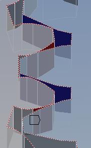
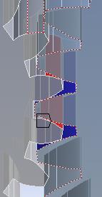
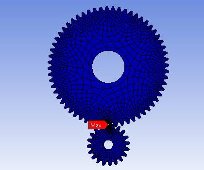
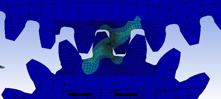
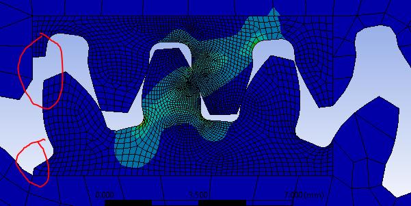
In the bottom image, look at the top gear; see how the stress contour line between blue and light blue has a discontinuity at the slice boundary? That is evidence that the slice boundary is too close to the teeth. Compare that to the bottom gear where the stress contour is smooth.
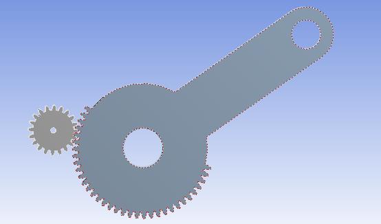
Gear teeth more than one tooth away have no effect on the stress result so you don't care about the shape of the mesh there. If you follow the pie slice approach, then you won't even have those teeth in the model.
While you are in DM doing the slicing, select all the bodies in the Outline, right click and select Form New Part. That will put all the pieces in a new multibody part with Shared Topology. That means the mesher will mesh across those bodies and you won't need any bonded contact to hold the pieces together.
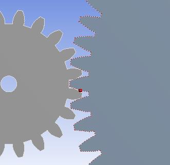
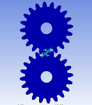
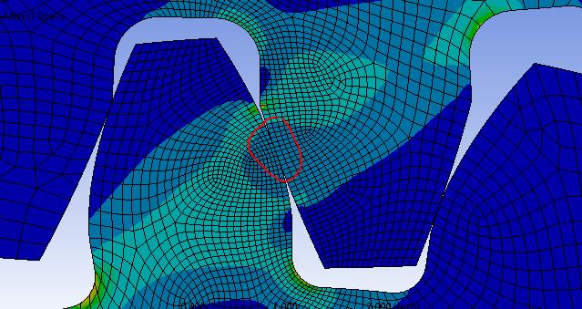
You don't show a legend in your contour plots so I don't know what you are plotting and there are many components available to plot. Some will have high values near the point of contact and others will have low values near the point of contact. You can also add a Contact Tool to the results and insert a Pressure result to see the surface pressure at the point of contact. That will definitely have its maximum value at the point of contact.
-
May 18, 2018 at 7:31 am
KeevKK
SubscriberThank you very much for your help. I appreciate it!
-
- The topic ‘Spur Gear FEM Analysis’ is closed to new replies.
-
6450
-
1906
-
1457
-
1308
-
1022
© 2026 Copyright ANSYS, Inc. All rights reserved.


