TAGGED: -Structured-Meshing, contacts, spur-gear
-
-
December 23, 2024 at 2:35 amharshanagasai668Subscriber
Hello,
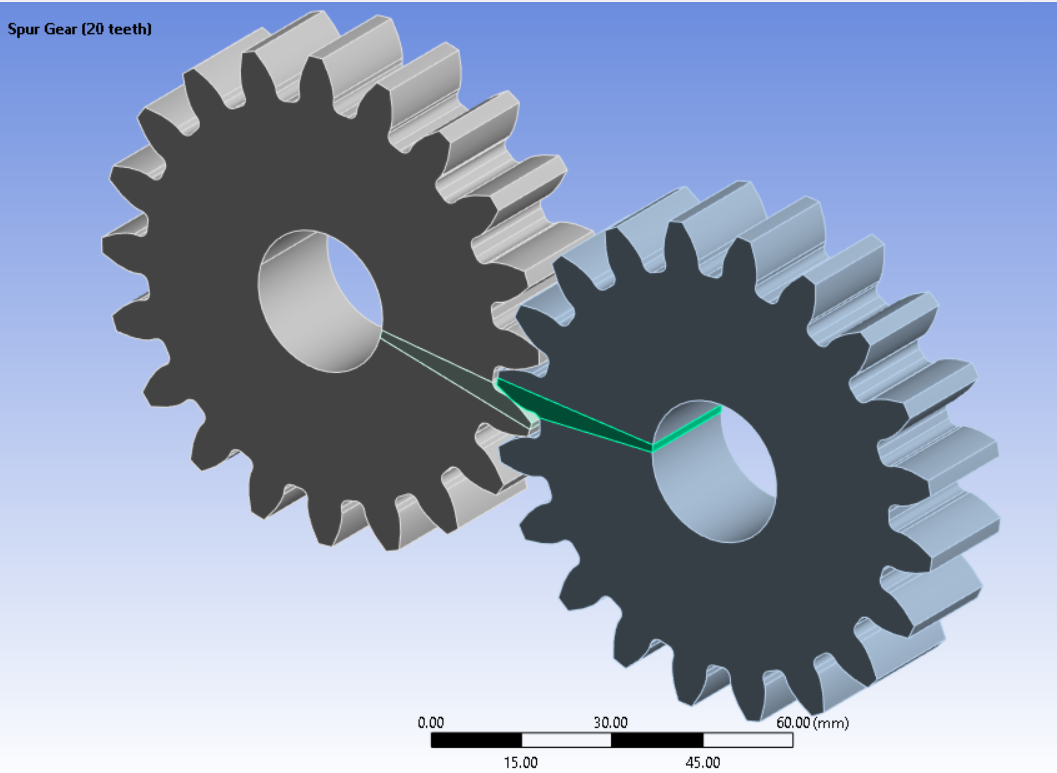
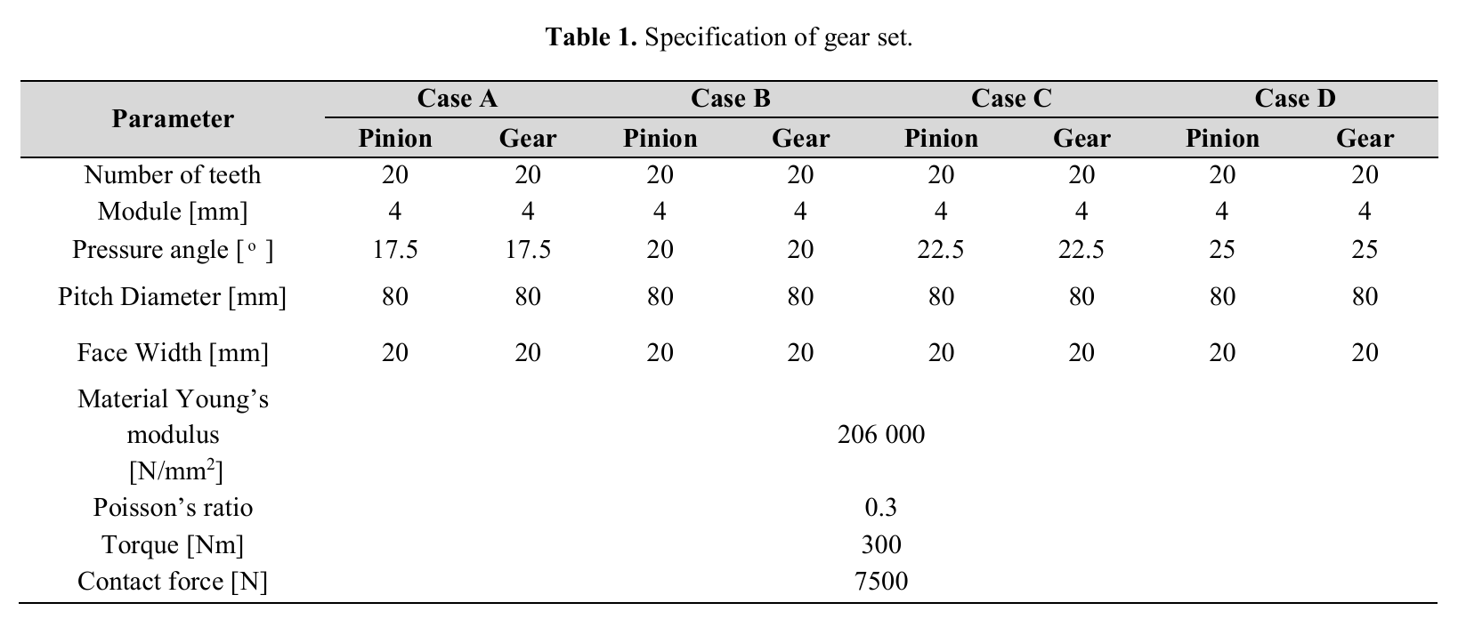
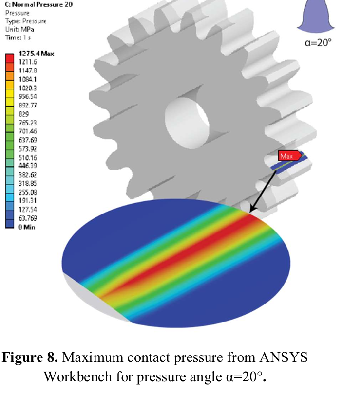
I attempted to simulate a spur gear based on a research paper where the contact stress is reported as approximately 1250 MPa; however, I am consistently obtaining 620 MPa. Here are the details of the gear that i considered. Case B is considered ie pressure angle of 20 degrees.
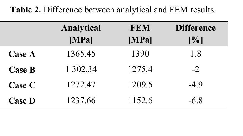
The contact stress according to the paper is
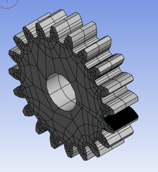
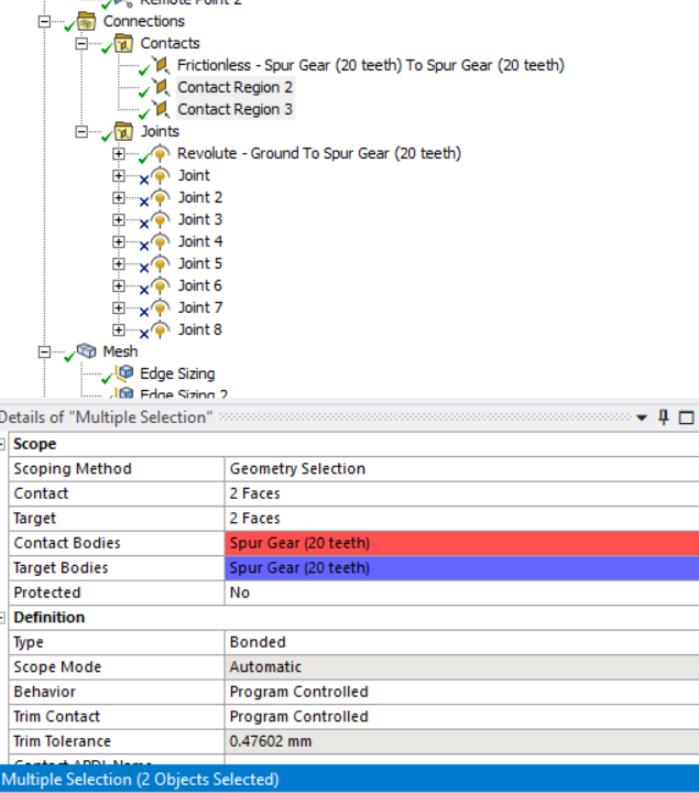
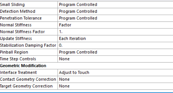
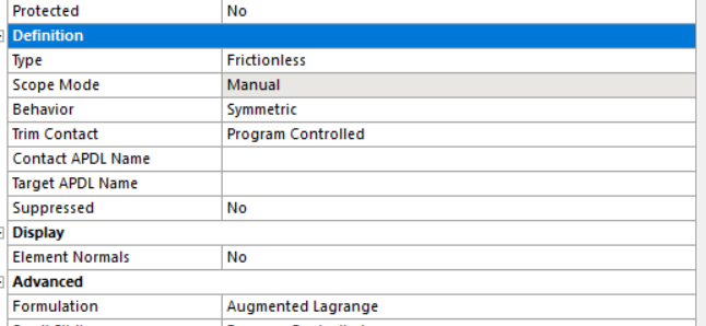
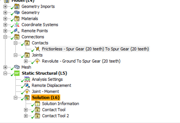
I even followed steps of previous posts here in ansys help, including using joints and joint loads for the moment, finely meshing the specific tooth, setting interface treatment to touch, enabling large deflection, and applying the moment to push the contact pair. Here is my setup in ansys.
I also experimented with material properties but wonder if, apart from modulus of elasticity, Poisson's ratio, and ultimate tensile strength, there are additional material properties I should define for accurate results.Despite running multiple iterations and exploring various contact options, I couldn't achieve the expected results. I even tested another model for verification but faced similar discrepancies.
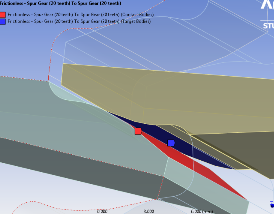
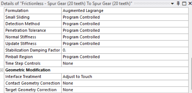
here are the contact options i implemented and i actually tried implementing normal stiffness factor of 1.
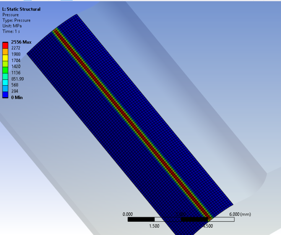
I switched on the auto time stepping along with it i also enabled all the output controls..here is the result i am getting.
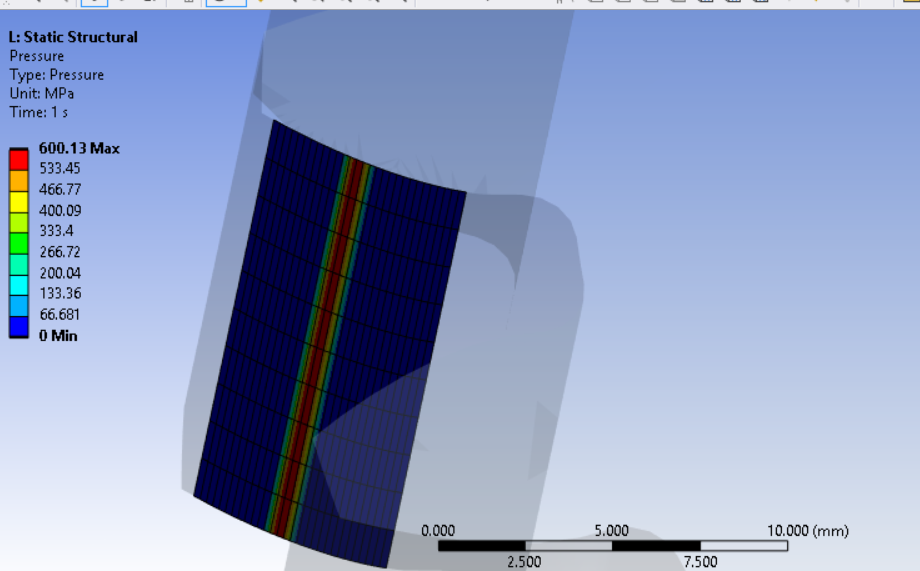
I would appreciate the community's help in this matter. Thank you -
December 23, 2024 at 12:19 pmLydia LymperopoulouAnsys Employee
Hello, I see that you are not using the most optimal mesh. Try to refine your mesh and make your elements look like cubes not orthogonals. I believe it will improve your results
-
December 27, 2024 at 5:21 pmharshanagasai668Subscriber
Â
Hello Madam, Thank you for your prompt response. Due to my academic license limitations on software, i am unable to fine mesh the entire gear setup. I tried other methods such as sphere of influence, but none of them worked . Which is why, i came up with Extrude CUT. But the solution is wayyyyyy off than the expected result.
Here only the portion of the tooth that are the focus of the analysis are fine meshed..as you mentioned..very thin cubes..I tried to refine them as much as possible.
I used the bonded joint btw the body and portions of the gear those were CUT.
And the contact btw these two gears are frictionless..and here are the details.
As mentioned in my previous request, the expected result should be around 1300 MPa..But the result i am getting with this approach is 2556 MPa.
Here is the result.
I would like to know what is going wrong with this approach. I sincerely request your help in this regard.Â
Note: As the pitch dia of the both pinion and gear is 80 mm, the center distance should be 80 mm. I hope i am not wrong here.
Thank you. I will await your response.Â
-
January 4, 2025 at 12:28 pmharshanagasai668Subscriber
Can anyone help here? I am stuck with this analysis and i dont want to manage the result i got..i want to learn the analysis of the gears. No shortcuts...So I really appreciate the help. Thank you
-
- You must be logged in to reply to this topic.
- How to apply Compression-only Support?
- At least one body has been found to have only 1 element in at least 2 directions
- Error when opening saved Workbench project
- Geometric stiffness matrix for solid elements
- Script Error Code:800a000d
- Timestep range set for animation export
- Image to file in Mechanical is bugged and does not show text
- Elastic limit load, Elastic-plastic limit load
- Element has excessive thickness change, distortion, is turning inside out
- BackGround Color
-
1557
-
602
-
599
-
591
-
366
© 2025 Copyright ANSYS, Inc. All rights reserved.