-
-
July 7, 2023 at 3:13 pm
andy.li2
SubscriberHello,
I have recently been working with Lumopt to design a 2D (FDTD) topology-optimized wavelength demultiplexer in silicon. However, I am noticing a significant difference in the performance of two simulated devices which should have identical performance.
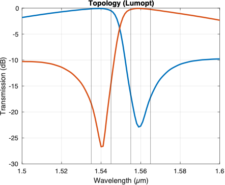
The first is the output of Lumopt, as shown below. This device has been fully binarized (no index values between silicon and oxide).
This device has the transmission spectrum shown below:
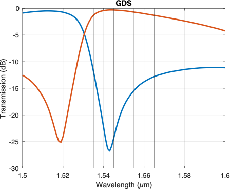
The second device is a direct GDS trace of the first device:

However, this has the transmission spectrum shown below:
As you can see, the spectrum is blue shifted by about 20 nm. By changing the FDTD mesh settings to use a uniform 20nm mesh (which the original device was optimized for) and aligning the mesh exactly with the device, the blue shift is reduced but still exists at about 5 nm. I have an optical index monitor on the entire device which shows no difference between the two devices. In both cases, I am using 2D FDTD simulation with PML boundaries.
Thanks for any help you can provide.
-
July 7, 2023 at 6:51 pm
Guilin Sun
Ansys EmployeeThank you for raising this question. As your test shows, results strongly depend on the mesh accuracy. and the geometry its self might have slight diference, as the GDS is represented by polygons. You may need to have the index data after simulation, and get their differece to see if the difference is exactly the same.
-
- The topic ‘Spectral variation between (n,k) import and GDS import of same device’ is closed to new replies.


-
3467
-
1057
-
1051
-
918
-
896

© 2025 Copyright ANSYS, Inc. All rights reserved.


