TAGGED: mechanical, static-structural, submodelling
-
-
June 26, 2025 at 6:33 am
yawfang
SubscriberHi all,
I just recently started to explore the use of submodelling in static structural with a simple model, but I encountered some problems in the process.
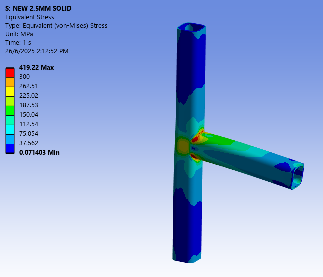
CONTROL CASE:
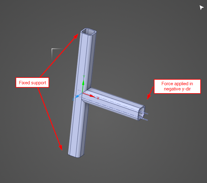
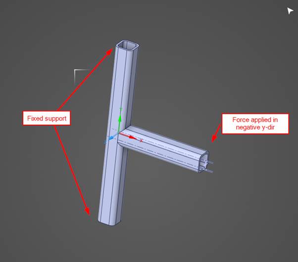
Two SHS 50X5 joined together as a T joint. Two ends are fixed and load is applied onto the remaining end.
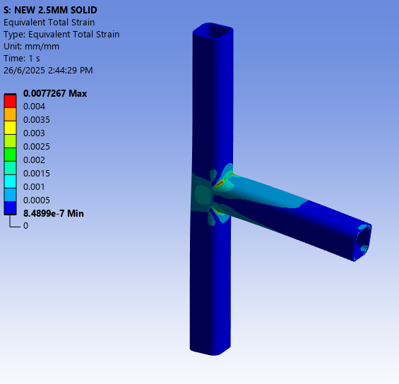
Mesh size is 2.5mm, and the result is as below.CASE 1 (SOLID-TO-SOLID):
Increase the mesh size up to 10mm (while face meshing the profile remains as two layers).
And then the joint (50mm distance from the joint) submodelled, with mesh size 2.5mm same as control case.
Stress distribution seems matched with the control case (although the area is larger and value is significantly higher).
CASE 2 (SHELL-TO-SOLID):
Midsurface the base solid model into shell model. Mesh size at 2.5mm same as control case.
And then submodel the joint (50mm distance from the joint) submodelled, with same mesh size 2.5mm
Stress values and area seems similar to control case, but some nodes at the cut surface are having high stress result, especially on the cut face.
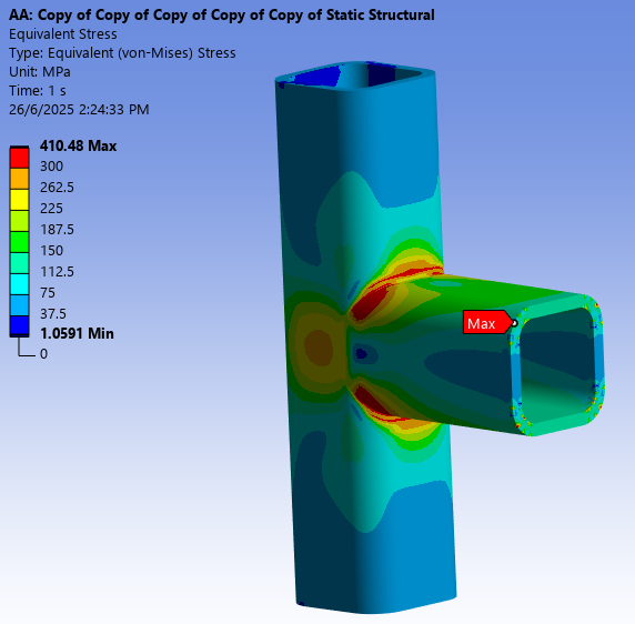
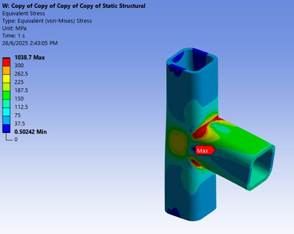
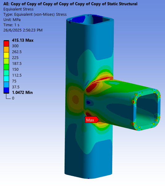
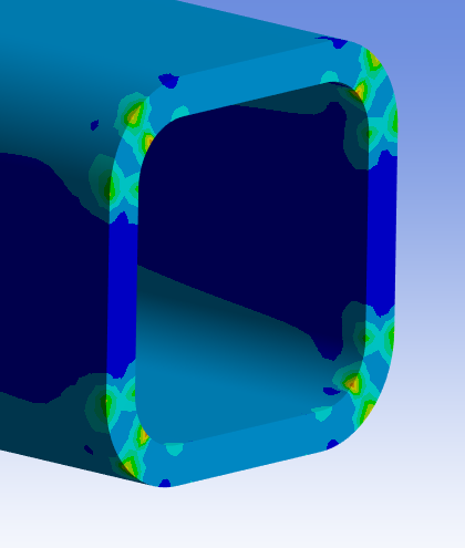
CASE 3 (SHELL-TO-SOLID):
Midsurface the base solid model into shell model. Mesh size set at 10mm.
And then submodel the joint (50mm distance from the joint) submodelled, with mesh size 2.5mm same as control case.
Stress values and area seems similar to Case 1, but some nodes at the cut surface are having high stress result, especially on the cut face too.

My questions are:
- How the initial mesh size of the "base" setup affect the result?
As from the result above, the base setups with mesh size 2.5mm have similar result (Control Case and Case 1).
Then another similar result for base setups with mesh size 10mm (Case 1 and Case 3).
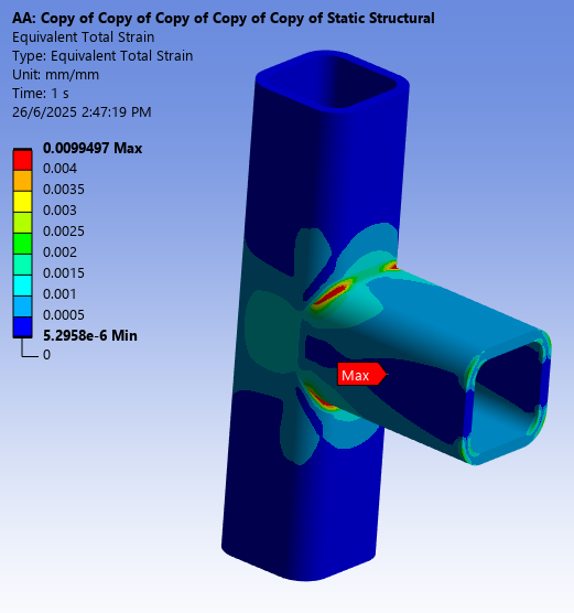
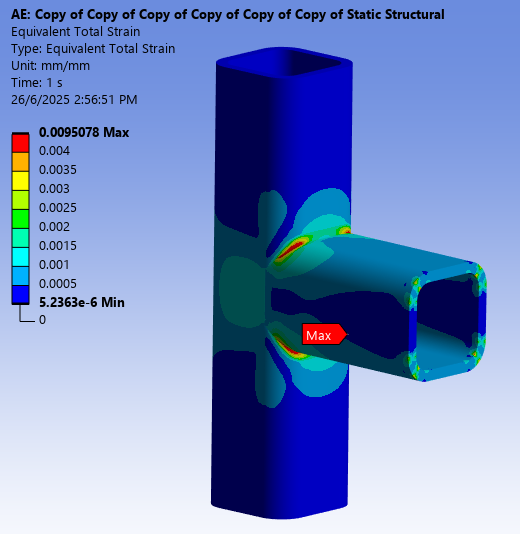
Just realized I should look at the strain result since I am running non-linear material properties. From strain result, the area seems similar. Attached the strain result. - 
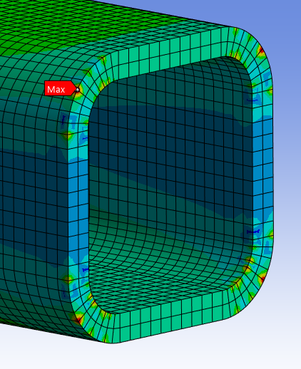
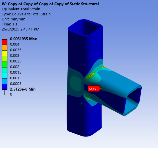
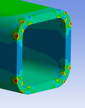
Why is it that some of the nodes at the cut surface is having irregularly high stress/strain points?
(Refer to the last picture in Case 3, although the value itself seems fine, but is relatively high compared to the surrounding nodes)
- How the initial mesh size of the "base" setup affect the result?
-
June 26, 2025 at 9:26 pm
peteroznewman
SubscriberThe cut planes that transfer boundary conditions from the global model to the submodel are known to have some amount of disturbance from the true solution. The way to handle that is to have the cut planes be far from the region of interest and to split the submodel body a short distance inboard from the cut plane to exclude solid elements adjacent to the cut plane and only report stress and strain on solid elements near the region of interest.
-
June 27, 2025 at 6:39 am
ErKo
Ansys EmployeeJust to emphasize how important it is to keep cut boundaries away from area of interest (called St. Venant's principle).
See here for some rec. :
https://ansyshelp.ansys.com/public/account/secured?returnurl=/Views/Secured/corp/v251/en/ans_adv/Hlp_G_ADV4UN.html?q=submodel
Ansys Help MAPDL Users Guide:
7.1. Understanding Submodeling
All the best
Erik -
July 2, 2025 at 1:29 pm
yawfang
SubscriberThanks Peter and Erik.
By the way, wish to check if there is any guideline like how far the cut boundaries should be away from the region of interest?
I read about the cut boundaries should have low stress gradient.
Which I thought one the area where the material is still in linear range should be sufficient.
But from my example, seems like my cut boundaries are not far enough. -
July 2, 2025 at 4:02 pm
peteroznewman
SubscriberGeneral guidance is to put the cut boundary at least 2 “characteristic lengths” away from the peak stress region. It looks like you have done that and we see the stress and strain have fallen greatly from the peak values.
The problem is the cut boundary submodeling process introduces artifacts in the stress and strain of the submodel. The mitigation is to split the submodel solid body a short distance inboard from the cut boundary, such as 4 elements. Split the submodel body in SpaceClaim and use the Share button on the Workbench tab so you won’t have any artifacts at these added split planes.
Only report stress and strain results in the main submodel body and don’t report stress and strain results on the short bodies split off the ends to exclude the stress and strain artifacts introduced by the submodeling boundary conditions on the ends of the short bodies.
-
- You must be logged in to reply to this topic.
-
5884
-
1906
-
1420
-
1306
-
1021
© 2026 Copyright ANSYS, Inc. All rights reserved.


