-
-
July 2, 2024 at 3:16 pm
john.dao
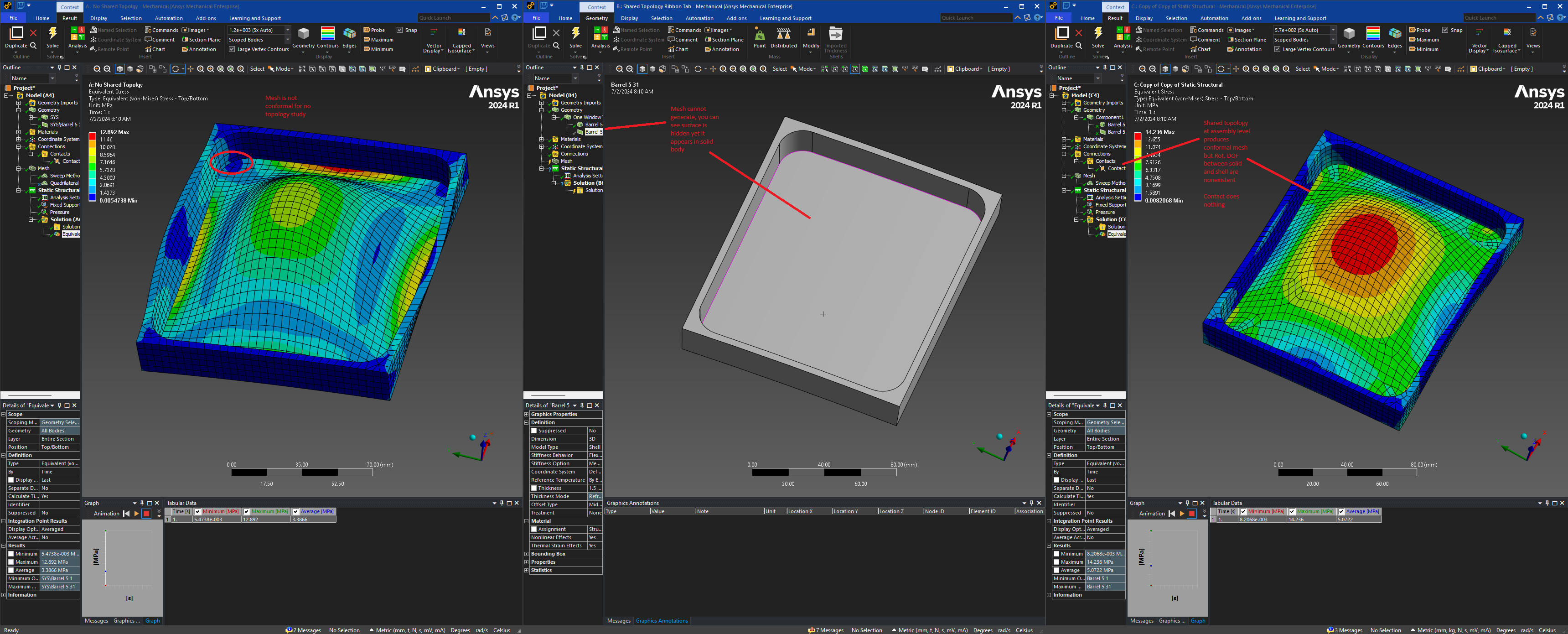
SubscriberI have a solid grid. My goal is to sweep mesh the ribs and quad shell the panels inbetween. I'm having a hard time figuring out the easiest workflow. Here are the things I do.
- Keep bodies separate, use contact, turn MPC on to capture rotations between Solid and Shell
- This method works but it is hard to maintain all these contacts as you can imagine there can be 9 full panels, each with 10-20 plate members
- It's also very hard to get a conformal mesh between the shells and solids
- Share Topology for each of the 9 full panels individually using the Spaceclaim "Workbench" ribbon bar
- This causes an issue with the solid body, the solid body will have the shells with it as one single part
- It will no longer mesh
- Put each panel in its own component with solid and shell, go to component properties -> Analysis -> Share Topology -> Select "Share"
Please help me find the easiest method to perform this task. I am using Ansys 2024 latest version as of this post with service pack 3
- Keep bodies separate, use contact, turn MPC on to capture rotations between Solid and Shell
-
July 4, 2024 at 8:38 pm
peteroznewman
SubscriberNodes on solid elements have no rotational DOF, while nodes on shell elements do have rotational DOF and as your found, if a surface edge is adjacent to a solid edge, a hinge is the result.
One method to get rotational connection between shell and solid elements along an edge is to overlap the shell with the solid. In your case, the you have the face of the solid rib. In SpaceClaim, it is simple to select that face and type Ctrl-C, Ctrl-V to copy the face and create a surface. Put that surface in the same component with the surface for the panel which is interior to the ribs. Use the Share button on the Workbench tab to share topology between those two surfaces. You can also share topology with the solid body.
In Mechanical, you should be able to mesh the panel and the surface created on the bottom face of the rib with shell elements and also mesh the solid body with solid elements. This results in the nodes on the bottom face of the ribs being connected to both a solid and a shell element.
When you turn on Thick Shells and Beams, you will notice that the shells on the bottom of the ribs are overlapping with the solid elements. This can be fixed by using an offset on the shell element to put the element thickness below the node instead on either side of the node. Then the shell thickness will not overlap with the solid elements. You should reduce the height of the rib by the thickness of the shell to keep the total thickness of the model with the offest shells correct.
You should also add a mesh control on the solid body to get two elements through the thickness of the rib as one element through the thickness of solid elements is less accurate for bending problems.
-
July 15, 2024 at 6:08 pm
john.dao
SubscriberThank you for replying. I had a lot of issues on this site and didn't see your reply until today. This is how I used to resolve this issue in FEMAP Nastran. I would produce a membrane mesh around the entire solid body, it essentially created a copy of the surface mesh as a shell. I would have to type in a thickness for this membrane. This would allow a conformal mesh between solids and shells and fix the rotational issues.
I have managed to recreate this workflow and it sounds very similar to what you descrbied. My only concern is the shell adding stiffness to the model in a modal analysis. I'm assuming that would be so?
-
- The topic ‘Solid to Shell issues when sharing topology’ is closed to new replies.


-
3467
-
1057
-
1051
-
918
-
896

© 2025 Copyright ANSYS, Inc. All rights reserved.


