-
-
July 8, 2020 at 9:00 pm
Eric_Eric
SubscriberHello All,
I am trying to model a cantilever structure with two sub-beams subjected to in-plane displacement constraints at the fixed end, as shown in the figure below. The in-plane displacement constraints cause bending and twisting deformation to the structure, which therefore becomes a bistable structure. I would like to do the analysis using Ansys and derive the nonlinear force-displacement curve. I tried to follow the example of VM17. The difference is that the structure is not buckling initially, instead, it's buckled after the first load step, e.g. applied in-plane displacement. Don't know if I need to do the buckling analysis firstly or not. I applied a displacement load at the free end of the cantilever according to suggestions in the forum but I am not sure it is the mentioned displacement control. I did get a curve after the analysis but it seems not what I expected a typical force-displacement curve of a bistable system with snap-through.Â
Could you please help check what's wrong with my simulation. I attached the APDL code here. Thank you very much.Â
-
July 11, 2020 at 12:42 am
peteroznewman
Subscriberfini
/clear
/RGB, index,100,100,100,0
/RGB, index,80,80,80,13
/RGB, index,60,60,60,14
/RGB, index,0,0,0,15
/prep7
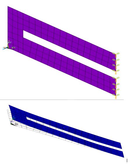
/title, unstable-structure
ET,1,SHELL63,,1
R,1,1.2e-3 ! SHELL THICKNESS
!Material properties of the alumina beam
Mp,ex,1,207e9
Mp,dens,1,8027
Mp,nuxy,1,0.32 !
!!!!!!!!!!!!!!!!!!!!!!!!!!!!!!!!!!!!!!!!!!!!!!!!!!!!!!!!
!Geomentric properties
lb1=105e-3
wb=45e-3
dwb=8e-3
thb1=1.312e-3
th=0.8e-3
dth1=(th-thb1)/2
thp=0.3e-3
lp1=28e-3
wp1=7e-3
lend=10e-3
llft=15e-3
wleg=(wb-dwb)/2
!!!!!!!!!!!!!!!!!!!!!!!!!!!!!!!!!!!!!!!!!!!!!!!!!!!!!!!!!!!!!!!!!!!
K,1,0,0
K,2,0,wb
K,3,llft,wb
K,4,llft,wleg+dwb
K,5,llft,wleg
K,6,llft,0
K,7,lb1,wb
K,8,lb1,wleg+dwb
K,9,lb1,wleg
K,10,lb1,0
A, 1,2,3,4,5,6
A,3,7,8,4
A,5,9,10,6
asel,all
Aglue,all
/view,1,1,1,1 !
/replot !
!!!!!!!!!!!!!!!!!!!!!!!!!!!!!!!!!!!!!!!!!!!!!!!!!!!!!!!!!!!!!!!!!!!!!!!!!!!!!
Smrtsize,5
mat,1
type,1
real,1
asel,all
amesh,all
Nummrg,node
eplot
/replot,e
/PNUM,MAT,0
fnode1=node(0,wb/2,0) ! get the number of the node at the certer of the free end
FINISH
!!!!!!!!!!!!!!!!!!!!!!!!!!!!!!!!!!!!!!!!!!!!!!!!!!!!!!!!!!!!!!!!!!!!!!!!!!!!!!!!!!!!!!!!!!
/PREP7
!! boundary conditions
nsel,s,loc,x,lb1
d,all,ux,0.0
d,all,uz,0.0
d,all,rotx,0.0
d,all,roty,0.0
d,all,rotz,0.0
nsel,all
FINI
/CONFIG,NRES,500000
/solu !
antype,static !
nlgeom,on !
outres,,1 !
!!Apply in-plane displacement loads
nsel,s,loc,x,lb1
nsel,r,loc,y,0,wleg
d,all,uy,dwb/3
nsel,all
nsel,s,loc,x,lb1
nsel,r,loc,y,wleg+dwb,wb
d,all,uy,-dwb/3
nsubst,5,50,5
nsel,all
solve ! solve load step 1
!! The structure is expected to be buckled and have two stable states due to the in-plane displacement loads
!!!!!!!!!!!Apply load at the free end
nsel,s,node,,fnode1
!d,all,uz,0.2e-3
F, all, Fz, -1! 1/4 TH OF THE TOTAL LOAD APPLIED DUE TO SYMMETRY
NSUBST,30 ! BEGIN WITH 30 SUBSTEPS
ARCLEN,ON,20 ! ARC-LENGTH SOLUTION TECHNIQUE TURNED ON WITH
nsel,all
SOLVE
FINISH
/POST26
NSOL,2,fnode1,U,Z ! STORE UY DISPLACEMENT OF NODE 1
PROD,4,1,,,LOAD,,,1! LOAD
!rforce,4,fnode1,f,z,reactionf
PROD,5,2,,,,,,-1 ! CHANGE SIGNS OF THE DISPLACEMENT VALUES
*GET,UY1,VARI,2,EXTREM,VMIN
PRVAR,2,4 ! PRINT STORED INFORMATION
/AXLAB,X, DEFLECTION (MM)
/AXLAB,Y, TOTAL LOAD (N)
/GRID,1
XVAR,5
PLVAR,4 ! PLOT LOAD WITH RESPECT TO -UY OF NODE fnode1 -
July 11, 2020 at 9:44 pm
Eric_Eric
SubscriberÂ
Hello Peter,
Thank you very much for your help. I run the code you revised and it does converge. But the result of the force-displacement curve is not the one I expect, which might be a typical nonlinear force-displacement curve of a bi-stable system, as illustrated in Fig.1 (a) below. This is because the structure should be a bi-stable structure, as shown in Fig. 1 (b). The in-plane displacement constraint is applied at the end of the two sub-beams, after which the end is fixed to keep the beam buckled. The buckled beam has two stable states and one unstable state. I am not sure if I should do buckling analysis in ANSYS by applying the in-plane displacement constraint firstly before I do the nonlinear force-displacement analysis.Â
I am very happy that I could communicate with you here and get your help.
Thank you very much.
-
July 11, 2020 at 10:17 pm
peteroznewman
SubscriberHello Eric,
The help I provided was to copy the model from your attached file and paste it into a post. I didn't revise the model. The reason I posted the contents of the attachment is because ANSYS staff are not permitted to open attachments, but the can reply to posts. So if anyone from ANSYS wanted to contribute, now they can.
I think you could get the typical snap through force-displacement profile if you started in one stable state and applied a moment to the center edges to get the structure to snap from one stable state to the other. You would plot moment and rotation instead of force and displacement. The reason I say moment instead of force is because if you applied a force to the center of the structure, it would bend about the fixed end too much and might not snap through.
Please reply with the force-displacement curve as the flat unbuckled beam has a displacement applied to move the ends together.
-
July 12, 2020 at 4:08 pm
Eric_Eric
SubscriberHello Peter,
Yes, I realized that later. Thank you for that and your advice on the moment load instead of the force at the free end.Â
Â
-
July 13, 2020 at 7:11 pm
peteroznewman
SubscriberGood Eric, please make a post with Is Solution to mark this Discussion as Solved.
-
July 13, 2020 at 8:14 pm
Eric_Eric
Subscriber
Good Eric, please make a post with Is Solution to mark this Discussion as Solved.
Â
Hello Peter,
Thank you for your reminder. I haven't figured it out yet and still want to see if someone here could give me more help.
I will post the reslut once I get it. Thanks.
Â
Â
-
- The topic ‘Snap through force-displacement curve’ is closed to new replies.
-
6189
-
1906
-
1452
-
1308
-
1022
© 2026 Copyright ANSYS, Inc. All rights reserved.

