-
-
February 23, 2022 at 10:26 am
Jose Mishael C J
SubscriberI am performing the static crack growth of a 3D object (a thin walled cylinder) with Semi Elliptical crack. I used SMART crack growth method for the static crack growth. I have to perform fatigue crack growth later.
I have few questions related with the post-processing of my static crack growth simulation results and implementation of number of contours for obtaining the results for fatigue crack growth simulation.
- Does the semi-elliptical crack grows in both directions during crack growth, i.e. does the minor radius (a) and major radius (c) increases during the crack growth? If both of them increase, how can I obtain the crack extensions in both directions? The crack extension probe provides only one value per crack front node. Is it 'a' or 'c' for the new crack?
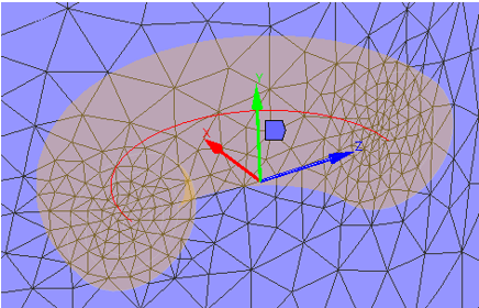
- Is there any possibility to visualize the semi-elliptical crack alone with the mesh around the crack tip? Something like as shown in the reference 'ANSYS Mechanical APDL Technology showcase Example problems' (Rectangular Block Geometry with Semicircular Surface Flaw and Sweep mesh around crack front, under Chapter - Evaluation of Mixed-Mode Stress intensity Factors and T-stress for 3-D Surface Flaws)
- During crack growth simulations, sometimes I received the following warning. ' Contour integration for crack 1 shows that some of contours are beyond the FE model and are to be modified. Please carefully evaluate the reported contour integral results. ' My understanding is that after crack growth, few contours may be outside the FE model and not able to considered in the fracture parameter integral calculations. Is there any way to reduce the number of contours as the simulation progresses? For example, during the beginning, I would like to consider 6 contours and as the crack progresses, the number of contours to be reduced into 4 or 5. This will be critical for the fatigue analysis of a thin walled structure.
I appreciate if someone can provide me some insights to resolve the problems.
March 3, 2022 at 6:18 amDavid Weed
Ansys Employee
Thank you for your questions; see my responses below.
1) A semi-elliptical crack will grow in all directions, but keep in mind that every node on the crack front has a local coordinate system, where the:
x-axis is the direction of crack growth
y-axis defines the direction normal to the crack plane
z-axis defines the direction tangent to the crack plane
See the MAPDL Fracture Analysis Guide, 2.1.3. Step 3: Define Crack Information: https://ansyshelp.ansys.com/account/secured?returnurl=/Views/Secured/corp/v221/en/ans_frac/fraccalcprocedure.html
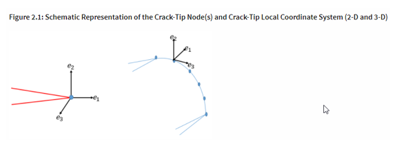 The crack-extension direction (e1), crack-plane normal (e2) at the tip, and the crack-tangent (e3) at the tip together constitute an orthonormal local coordinate system at the crack tip.
A scalar value for the crack extension increment is sufficient to represent crack growth. In the case that you have mixed-mode crack growth, in a fatigue scenario, the direction of the crack may change. In that case, if you wish to know the crack direction, you can use the formula in the MAPDL Fracture Analysis Guide, 3.1.3.1. Paris' Law:

As an aside, it may be helpful to see how the crack is setup using APDL commands and subsequently visualize the local coordinate systems for each node along the crack front. In Mechanical, if you open the ds.dat file (located in the Solver Files directory), you can see how the crack is setup using APDL commands:
cint,ctnc,NS_SECRACK_FRONT,_iAssistNode! Define crack tip node component
cint,ncon,3! Define number of contours
cint,normal,13,2! Define crack plane normal
You can read more about these commands and how they define the crack in the MAPDL Fracture Analysis Guide, 2.1.3.1. Define the Crack-Tip Node Component and Crack-Plane Normal (CINT,CTNC): https://ansyshelp.ansys.com/account/secured?returnurl=/Views/Secured/corp/v221/en/ans_frac/fraccalcprocedure.html
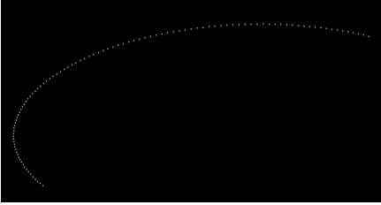
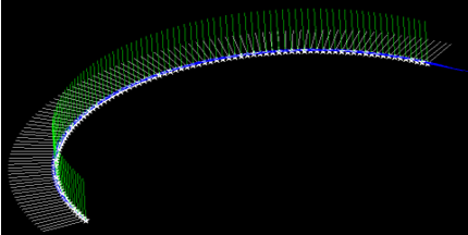
To visualize the local coordinate systems, load the ds.dat into MAPDL, select the nodes along the crack front (using the Named Selection, NS_SECRACK_FRONT and the CMSEL command) and issue the command CINT,PLOT,1 (where '1' is the crack ID). See the plot of the nodes and then the local coordinate systems:
2) It appears that in the Tech Demo showcase, a separate crack mesh was created and brought into Mechanical. In contrast, when you use the native semi-elliptical crack object, you can't visualize the bodies separately in the same way as the graphic shows. However, if you have the mesh view toggled on and highlight the semi-elliptical crack object, you can see an outline of the contours overlaid onto the crack mesh:
3) During crack growth simulations, sometimes I received the following warning. ' Contour integration for crack 1 shows that some of contours are beyond the FE model and are to be modified. Please carefully evaluate the reported contour integral results. ' My understanding is that after crack growth, few contours may be outside the FE model and not able to considered in the fracture parameter integral calculations. Is there any way to reduce the number of contours as the simulation progresses? For example, during the beginning, I would like to consider 6 contours and as the crack progresses, the number of contours to be reduced into 4 or 5. This will be critical for the fatigue analysis of a thin walled structure.
One approach is to use the CINT,NCON command to adjust the contours during the analysis. However, for crack growth analysis, the suggested method is to use the CGROW,RMCONT,ESIZE command. It allows you to adjust the size of the mesh as the crack approaches the boundary. Essentially, with a smaller element size, the calculated crack extension increment will be smaller, which can help the fracture contours to remain inside of the FE domain. You may consider using a table to adjust the element size using the aforementioned command so that you can better control when the mesh will become more fine, particularly at the FE boundary. For information on that command, I would recommend reading this help section in the MAPDL Fracture Guide, 3.2.1.6. Crack-Growth Dynamic Crack-Increment Control: https://ansyshelp.ansys.com/account/secured?returnurl=/Views/Secured/corp/v221/en/ans_frac/fracSMART.html
I hope that this information is helpful to you.
March 3, 2022 at 10:14 amJose Mishael C J
SubscriberThank you very much for the detailed explanation.March 3, 2022 at 6:58 pmDavid Weed
Ansys Employeeyou're welcome and let me know if you have any follow up questions.
April 3, 2022 at 7:38 pmTomC
SubscriberI have a question in this vein. I'm running some models where cracks on the ~10 micron scale grow until failure on the 1000 microns scale.
It's not computationally efficient to run the same mesh required at 10 microns all the way out to 1000 microns. With Pre-meshed Cracks, I just run the geometry in steps and it works fairly well. With Semi-Elliptical cracks, I could do the same, but I'm not sure how to match the size of the minor and major radius between models. If I have a 20 um x 100 um crack that I run 10 substeps of SMART crack growth on, it seems inaccurate to say that the new, coarser mesh model will be 20+Crack Extension x 100+Crack Extension.
I'm not sure where to find the information I need to define a new, larger crack (with a correspondingly coarser mesh).
February 22, 2023 at 8:41 pmDivya Giri
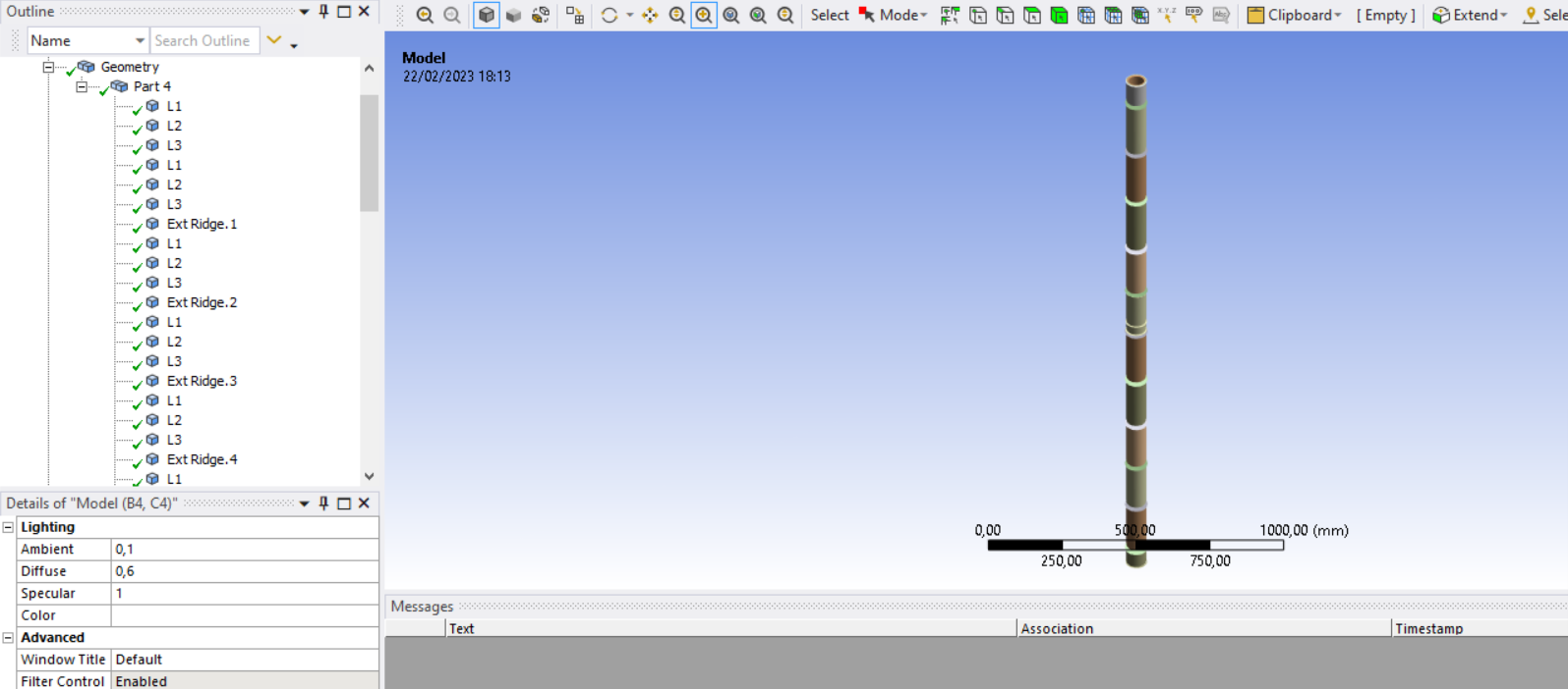
SubscriberHello,I need to model a crack as 'pre-damage' in a bamboo culm model, but since my model is a combination of different parts, I couldn't generate a crack on it. I tried shared topology as well and tried generating a semi-elliptical crack, but I would only get the errors stating that the arbitrary crack cannot find an anchor surface. I would be really grateful if someone could help me through this.I have attached an image of my model for more clarity.Thank you in advance.Regards,November 30, 2023 at 5:43 pmBD1995
SubscriberCan someone show exaple how to write commands to adjust mesh during the analysis as the crack approaches the boundary. I'm doing crack calculation on the thin walled pipe? Thanks in advance.
Viewing 6 reply threads- The topic ‘SMART Crack Growth with Semi-elliptical crack’ is closed to new replies.
Ansys Innovation SpaceTrending discussionsTop Contributors-
3387
-
1052
-
1050
-
886
-
852
Top Rated Tags© 2025 Copyright ANSYS, Inc. All rights reserved.
Ansys does not support the usage of unauthorized Ansys software. Please visit www.ansys.com to obtain an official distribution.
-
The Ansys Learning Forum is a public forum. You are prohibited from providing (i) information that is confidential to You, your employer, or any third party, (ii) Personal Data or individually identifiable health information, (iii) any information that is U.S. Government Classified, Controlled Unclassified Information, International Traffic in Arms Regulators (ITAR) or Export Administration Regulators (EAR) controlled or otherwise have been determined by the United States Government or by a foreign government to require protection against unauthorized disclosure for reasons of national security, or (iv) topics or information restricted by the People's Republic of China data protection and privacy laws.


