-
-
December 11, 2024 at 4:33 pmSeyyed Mahmoud MousaviSubscriber
Dear all,
Â
I am trying to model water wave propagation in a 3D open channel domain. My flume of interest, has a slanted bed, say 1:74Â slope in y direction, please see the below picture.
In outflow BC, what should I enter for the bottom level? The bottom left corner location is (x,y) = (0,0) m, but the bottom right corner location is (x,y) = (10 , 0.14) m.
-
December 12, 2024 at 10:19 amRobForum Moderator
I've not tried that recently, but from memory, I think you set the bottom of the boundary.Â
-
December 14, 2024 at 12:06 pmSeyyed Mahmoud MousaviSubscriber
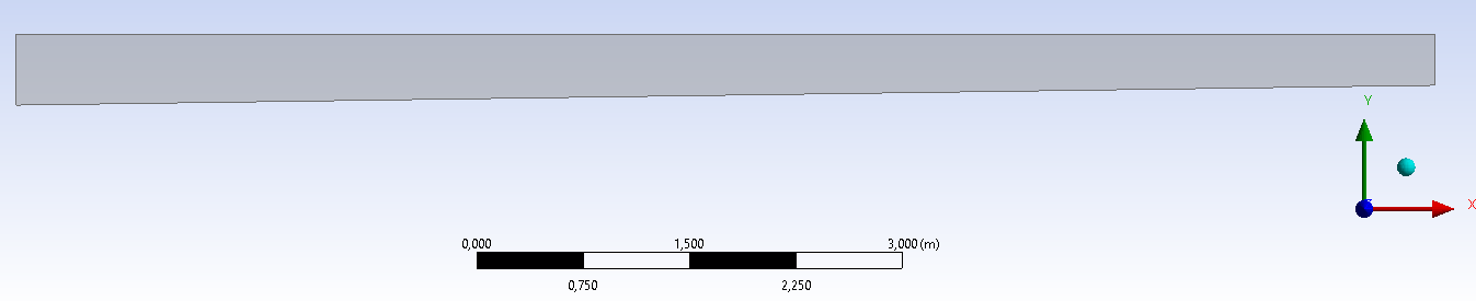
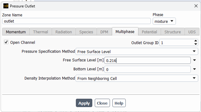
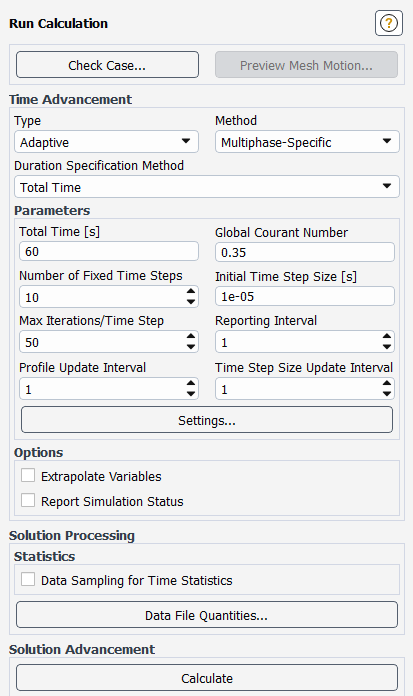
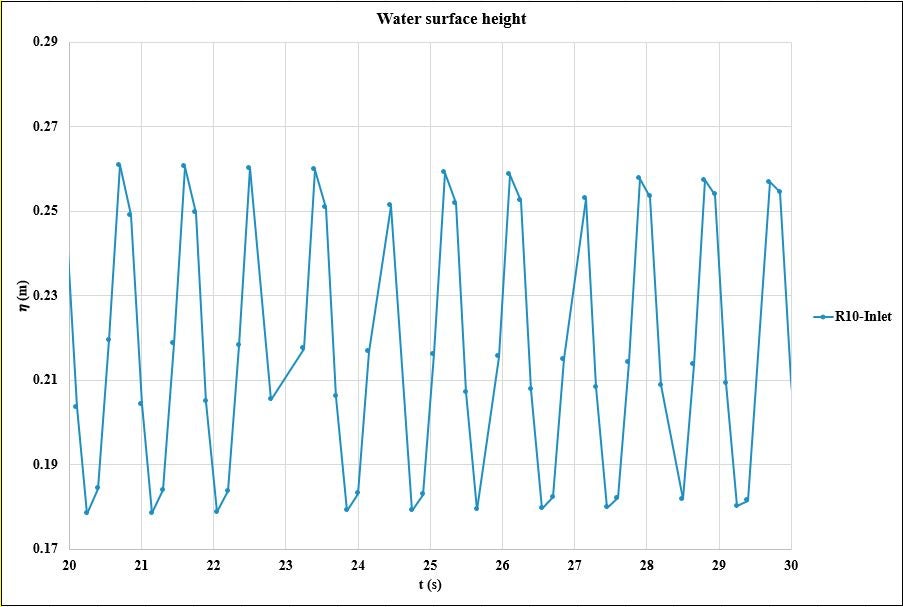
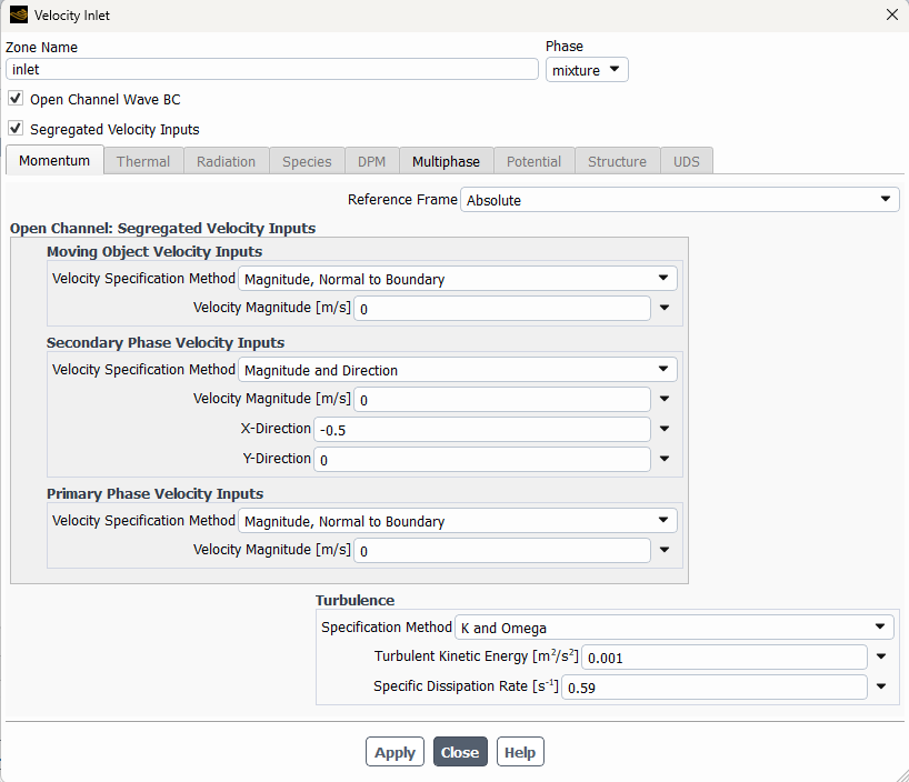
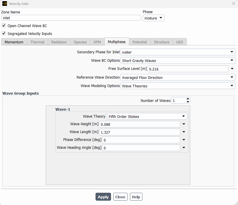
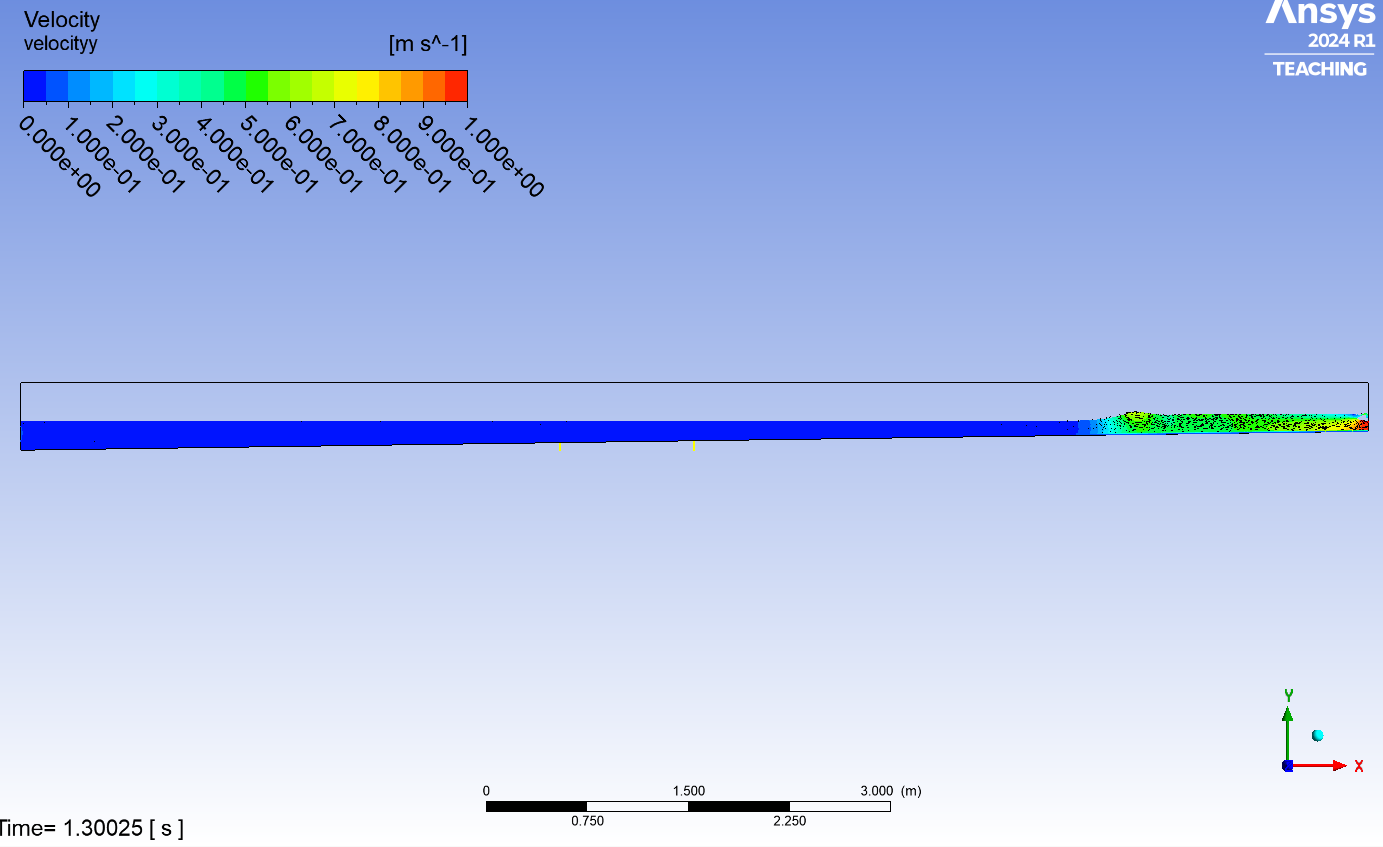
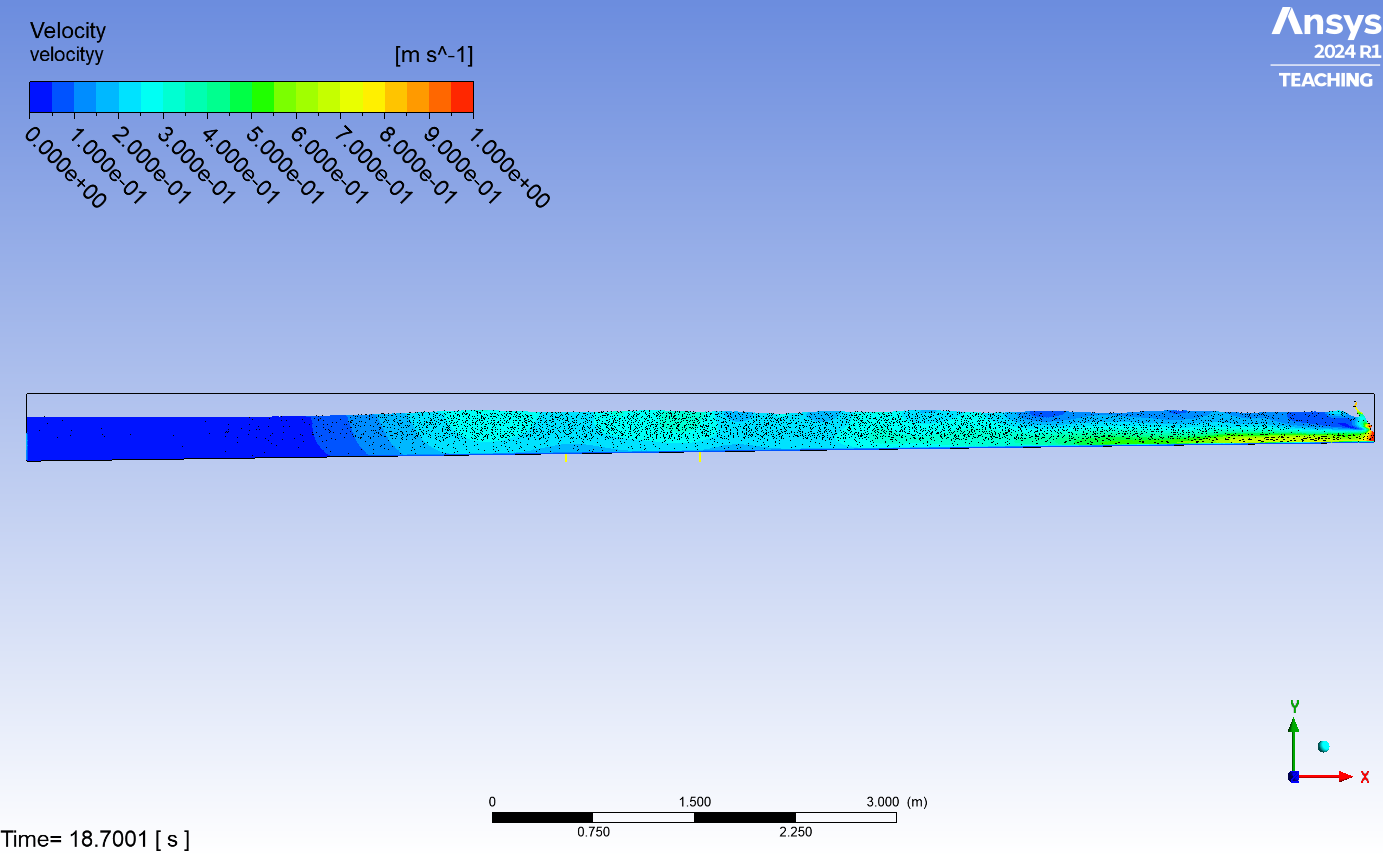
Ok, I understand. Given the wave condition propagating from the inlet boundary, H = 0.088 m and T = 1.05 s, theoretically we expect wave breaking somewhere in the flume where water depth becomes lesser than the inlet. On the other hand, in ANSYS, we can choose only airy (linear) wave theories as the open channel BC. Does that mean we cannot imply or simulate this wave condition with this conventional BC that is already available in Fluent? Because I am receiving the floating exception error, while I reduce the wave height (to avoid wave breaking), the model works. In this case, what can be the solution or alternatives to this matter where the wave most probably breaks?
I was thinking, instead of applying the open channel wave BC at the inlet, maybe I should simulate a wave generator (by moving mesh boundary) at the inlet of the domain and let the Fluent solver physically develop the propagation of the wave in our computational flume?
Thanks! -
December 16, 2024 at 9:59 amRobForum Moderator
Floating point is likely divergence, so is more likely related to the solution changing too quickly or an interaction of the free surface with the mesh.Â
-
December 16, 2024 at 1:58 pmSeyyed Mahmoud MousaviSubscriber
So, if I understood correctly, you are suggesting decreasing the time step? I have already tried several time steps, I always got the Floating Point error. The only case I could run the simulation successfully is when I am reducing the wave height from ~ 9 cm to ~ 5 cm.
Or what are the other suggestions to overcome that error?
-
December 16, 2024 at 2:14 pmRobForum Moderator
If reducing the wave height works it's because it's removing a model instability, reducing the time step will reduce the impact of the instability on the solution hence me suggesting it. Note, the step might become very small. You also need to check the cell size and shape as the wave enters the domain: how many cells are across the amplitude and how low is the aspect ratio.Â
-
December 19, 2024 at 9:19 amSeyyed Mahmoud MousaviSubscriber
Hi Rob!
I followed your suggestion to decrease the time step. I set the Adaptive time step with CFL = 0.35, and initial time step size = 1e-5 (s). Fortunately the solution has been converged.Â
I have another question: I set to save the outputs every 0.15 (s) of the flow time. However, there are some time intervals, that the outputs are not saved at each 0.15 (s), but they are saved in bigger time intervals. This makes the output look like with some missing data. How can I make sure that Fluent will save every 0.15 (s) of outputs?
-
December 19, 2024 at 12:00 pmRobForum Moderator
I think it'll pick the nearest time step, so you may want to check what the maximum permitted step size is. If you're wanting a surface height you can also monitor, plot and save that directly as you run the model: look at the Report function.Â
-
December 19, 2024 at 12:05 pmSeyyed Mahmoud MousaviSubscriber
Thanks for the reply.
1- Where/how can I check the "what the maximum permitted step size is"?
2- "If you're wanting a surface height you can also monitor...", again how? Should I choose something like facet and then max facet speed or what?
Â
Could you please assist with those questions?
-
December 19, 2024 at 12:07 pmRobForum Moderator
Check the Settings in the iterate panel - adaptive time stepping has controls that may need checking.Â
Have a look on here for "depth" and the like - I've answered a similar question fairly recently.Â
-
January 7, 2025 at 4:13 pmSeyyed Mahmoud MousaviSubscriber
Hello again and happy holidays!
I could run a 2-D simulation of water wave propagations (from the left wall to the right wall of the channel) in my computational domain (as shown in the first picture of this topic). This computation, took approximately 1 day to be completed. Subsequently, I wanted to include the discharge of a flow into my domain as well (from right to left) together with the wave propagation (as in the previous model). Everything else remained similar to the previous model (the model with only wave propagation). However, this time, the simulation is taking more than 5 days, where the simulation has been interrupted in day 6th (I don't know yet why it collapsed). My primary question is that, is it logical (does it make sense) that including a discharge of a flow into my other end side of the BC, should cause increasing the computational costs from one day to more than 5 days?
Â
Thanks!
-
January 7, 2025 at 4:18 pmRobForum Moderator
Merry Christmas & Happy New Year!Â
Speed is a function of cell count, but time (duration) can also be iteration & time step count: do you mean the same number of iterations takes longer?Â
-
January 7, 2025 at 4:21 pmSeyyed Mahmoud MousaviSubscriber
Yes, I kept all the numerical settings and configurations and iterations the same. The time step is based on the CFL number (assigned to be 0.35) not a fix value by myself, though I kept the CFL number the same between these 2 models.
-
January 7, 2025 at 4:33 pmRobForum Moderator
Is the solver needing more iterations per time step? How many more cells did the outlet add? Does the outlet change the flow velocity in the system?Â
-
January 13, 2025 at 8:56 amSeyyed Mahmoud MousaviSubscriber
Hi Rob!
I solved the time-step issue with your suggestions. Another question: I am applying a wave BC at the inlet of my domain where I chose "Wave BC Options: Short Gravity Waves." My question is, what are the governing equations that are solved inside the domain? Are Navier Stokes equations applied to solve the inner domain? I mean, the option "Short Gravity Waves" is applied only at the inlet of the domain to generate waves and then the wave propagation inside the domain is solved by N-S equations or no the entire domain is governed by Short Gravity Waves equations?
I hope I could be clear on my question and I can provide more details if necessary.
Â
Thanks again!
-
January 13, 2025 at 11:09 amRobForum Moderator
It's a boundary condition to generate waves based on the wave theory. Fluent solves the normal N-S maths in the cell zone.Â
-
January 16, 2025 at 1:50 pmSeyyed Mahmoud MousaviSubscriber
Hi Rob!
Â
I am applying a regular wave propagation condition at the inlet of my domain. At the same time, I am applying a current velocity at the outlet of my computational domain toward the inlet (to flow inside the domain to study the wave-current interaction). How can I let the incoming flow generating from the outlet boundary side pass through the inlet side (where waves are generating) of my domain while the inlet BC is open-channel wave?
Â
Thanks as always!
-
January 16, 2025 at 5:11 pmRobForum Moderator
So the wave is travelling against the current? Have a look at the boundary options re inlet direction vector.Â
-
January 16, 2025 at 6:18 pmSeyyed Mahmoud MousaviSubscriber
Yes, Rob! Waves are travelling from the inlet boundary against the flow which is coming from the outlet boundary. Could you please specify better what do you mean by "look at the boundary options re inlet direction vector"? I mean what are you suggesting to resolve the issue?
I want the current flow to move out from the inlet boundary location when it reaches there. However, the inlet boundary location is assigned as a wave BC.
Â
Thanks!
-
January 17, 2025 at 11:45 amRobForum Moderator
You can set flow speed to be different from the wave boundaries - hence checking whether you can set flow out via the inlet.Â
-
January 17, 2025 at 4:02 pmSeyyed Mahmoud MousaviSubscriber
Ok, that is exactly my question? I mean how I can assign an outflow to my inlet boundary location, while I have already assigned a wave BC at the inlet of my domain?
-
January 17, 2025 at 4:16 pmRobForum Moderator
Have you looked at the options in the boundaries? Specifically things like direction vector.Â
-
January 17, 2025 at 4:20 pmSeyyed Mahmoud MousaviSubscriber
I am not sure if we are talking about the same issue. My problem is not the direction vector. My problem is, my inlet domain has been assigned a wave BC. At the same time, I need the flow which is coming from the outlet boundary location toward the inlet side, to pass through the inlet side. How I can assign 2 different BCs at the inlet side?
-
January 20, 2025 at 2:07 pmRobForum Moderator
You don't, but with the various options for flow vector, can you set a negative velocity on the inlet and waves? I've run cross flow waves at various angles but not full counter-current before.Â
-
January 21, 2025 at 11:06 amSeyyed Mahmoud MousaviSubscriber
Good morning Rob (in Italy is morning now)!
I tried to change the inlet BC from Wave only to Wave and Current as shown in the below picture. Basically, in addition to the wave BC which should propagate from the inlet into the computational domain, I tried to add some negative velocity values to the secondary phase (water) at the inlet. I am adding this negative velocity value at the inlet, ONLY to (hopefully) resolve the issue of the water flow accumulation which is coming from the outlet of my domain (I need to find a way to drain this water when it reaches at the inlet of my domain).Â
Â
However, this did not help to resolve the issue. With this BC, I could not see any wave propagation at the inlet (the left wall) of my domain. Also, the water height in my flume got increased. Please see the below pictures.
Â
So any suggestions to resolve the wave+current interaction at the inlet boundary (which should be wave propagating)?
Thanks! -
January 21, 2025 at 1:34 pmRobForum Moderator
And setting wave reference direction to vector doesn't help?Â
-
January 23, 2025 at 6:31 pmSeyyed Mahmoud MousaviSubscriber
Ok! Setting wave reference direction to vector helps to make the wave and flow propagate at different directions at the inlet of my domain, Thank you!
My next question is, how can I assign the flow velocity at the out let of my domain only to the water portion (not to the air phase)? Likely, I need to apply the wave BC at the inlet only to the water phase not the air phase. Whenever I change the phase from mixture to water in the BC, the BC window changes like I cannot specify any flow velocity or anything. However, when I changed the option to mixture, I can assign the flow velocity magnitude and so on, but I want to assign these conditions only to water.
-
January 24, 2025 at 8:44 amSeyyed Mahmoud MousaviSubscriber
I tried to inquire about the last question in a new post with a greater detail.
Fluent multiphase different BCs
-
-
January 24, 2025 at 10:21 amRobForum Moderator
OK, that's fine. I'll close this thread.Â
-
- You must be logged in to reply to this topic.
- How do I get my hands on Ansys Rocky DEM
- Non-Intersected faces found for matching interface periodic-walls
- Fluent fails with Intel MPI protocol on 2 nodes
- Unburnt Hydrocarbons contour in ANSYS FORTE for sector mesh
- Help: About the expression of turbulent viscosity in Realizable k-e model
- Cyclone (Stairmand) simulation using RSM
- Mass Conservation Issue in Methane Pyrolysis Shock Tube Simulation
- Script Error
- Facing trouble regarding setting up boundary conditions for SOEC Modeling
- convergence issue for transonic flow
-
1602
-
602
-
599
-
591
-
366
© 2025 Copyright ANSYS, Inc. All rights reserved.