-
-
June 26, 2023 at 6:18 pm
Rohan Patel
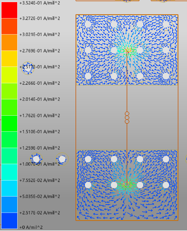
SubscriberWhen looking at the current density of a voltage rail that has a series inductor or a series sense resistor, the current flows to a singlular point that is shown as an inductor or resistor respectively. Since the current flows to this single point the current density is shown to be extremely high which is not the case realistically since the pin of the component is much larger. Is there a way to represent the pin of the inductor or resistor as its physical size instead of a single point in SIwave? See image for context
Thank you
-
June 28, 2023 at 2:52 pm
Mrinmoy Bharadwaj
Ansys EmployeeSIwave does not include the physical dimensions of the components (R,L,C) into the simulation because they are not needed since the component values and/or its parasitics (mounting inductance/resistance etc.) are already specified in the model. You can visually see the a 3D representative view of R,L and C components in your board by unchecking the "2D View" and "Simplyfy Circuit Elements" options under the view tab. However, these are only visual and does not affect simulation results. DCIR is intended to check the board elements such as planes, pads, traces, vias etc.
-
- The topic ‘SIwave DC IR Drop Simulation Question’ is closed to new replies.


-
3427
-
1057
-
1051
-
896
-
887

© 2025 Copyright ANSYS, Inc. All rights reserved.


