Ansys Assistant will be unavailable on the Learning Forum starting January 30. An upgraded version is coming soon. We apologize for any inconvenience and appreciate your patience. Stay tuned for updates.
LS Dyna

LS Dyna

Topics related to LS-DYNA, Autodyn, Explicit STR and more.

Simulation of contact between suction cup and rigid part

TAGGED: ,

    • b.mavroeidis2
      Subscriber

      I am trying to simulate the attachment between a rubber suction cup and a rigid/plastic part due to vacuum pressure

      Current setup

      • Hyperelastic suction cup (Mooney-Rivlin)
      • Frictional contact between cup and part
      • Negative pressure applied on internal cup surfaces

      Problem

      The vacuum pressure deforms the cup, but the part separates instead of remaining attached. It seems the pressure only acts on the cup and does not generate the expected suction holding force on the part.

      Questions

      1. What is the correct way to model vacuum suction contact?
      2. Is internal negative pressure alone sufficient?
      3. How should the pressure transfer to the contacted part be modeled?
      4. Is there a recommended method in LS-DYNA or ANSYS Mechanical for suction cup attachment simulations?

      Any guidance or example workflows would be appreciated

    • peteroznewman
      Subscriber

      Can you share your model so I can try something out?  If so, in Workbench use File, Archive to save a .wbpz file.  Upload that file (not the .wbpj file) to a file sharing site such as Google Drive.  Set Sharing on that file so that Anyone with the link can download.  Reply with the link. I will let you know what worked using Ansys Mechanical.  Others may have suggestions for how to do this in LS-Dyna.

    • peteroznewman
      Subscriber

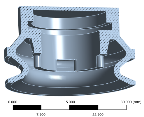
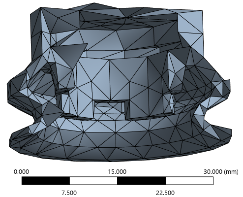
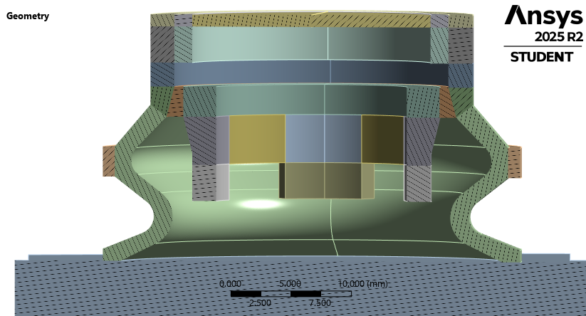
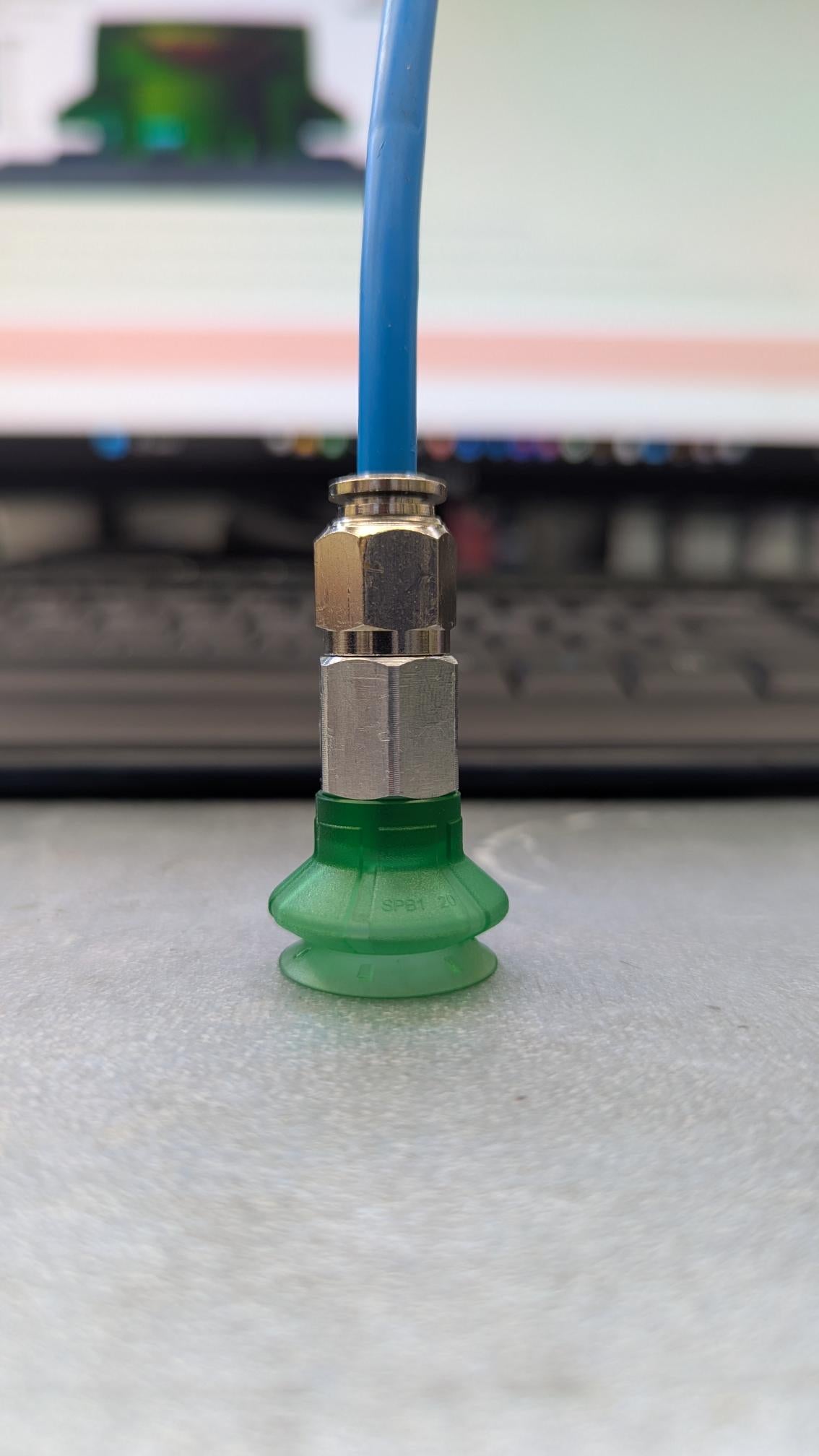
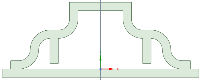
      Here is a cross-section of a suction cup sitting on a base plate.

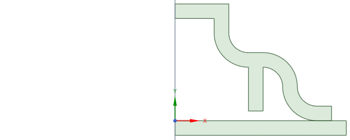
      Since this is axisymmetric geometry and I will apply axisymmetric loads, I will solve this as an axisymmetric model which means I only mesh the radial slice on the X-Y plane.

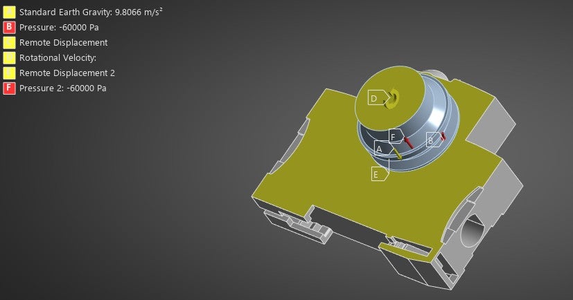
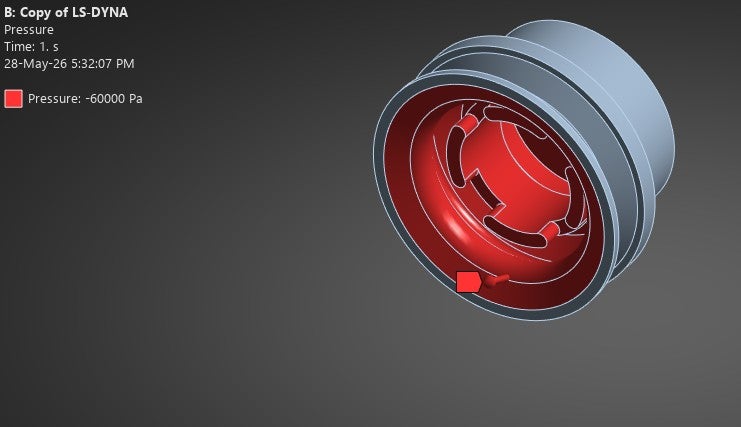
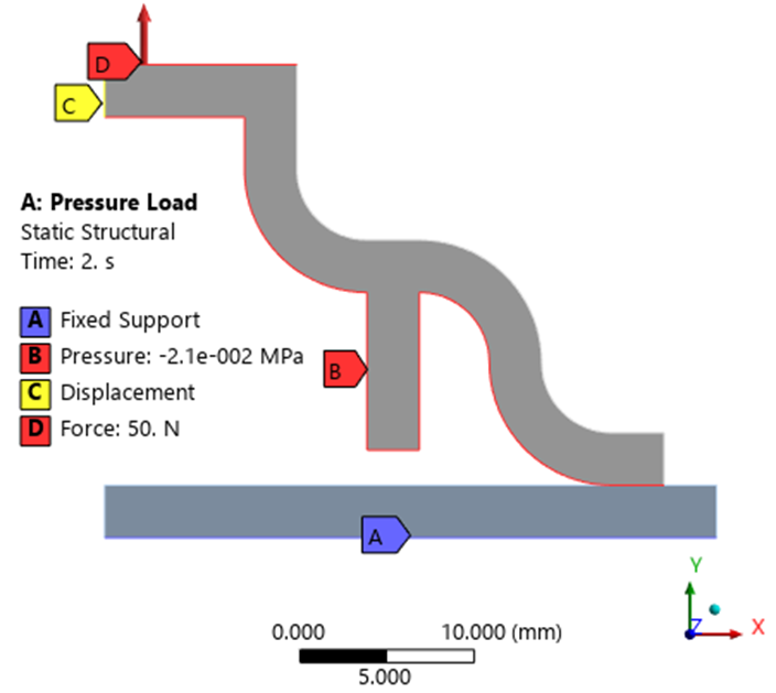
      There are two models, one has a negative (vacuum) pressure on the inside faces of the suction cup and a lift force on the top in a two step analysis.

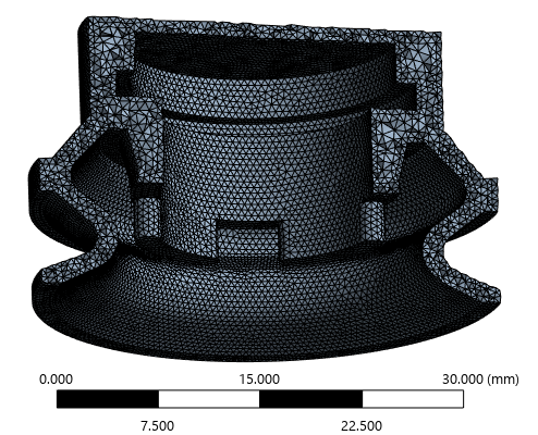
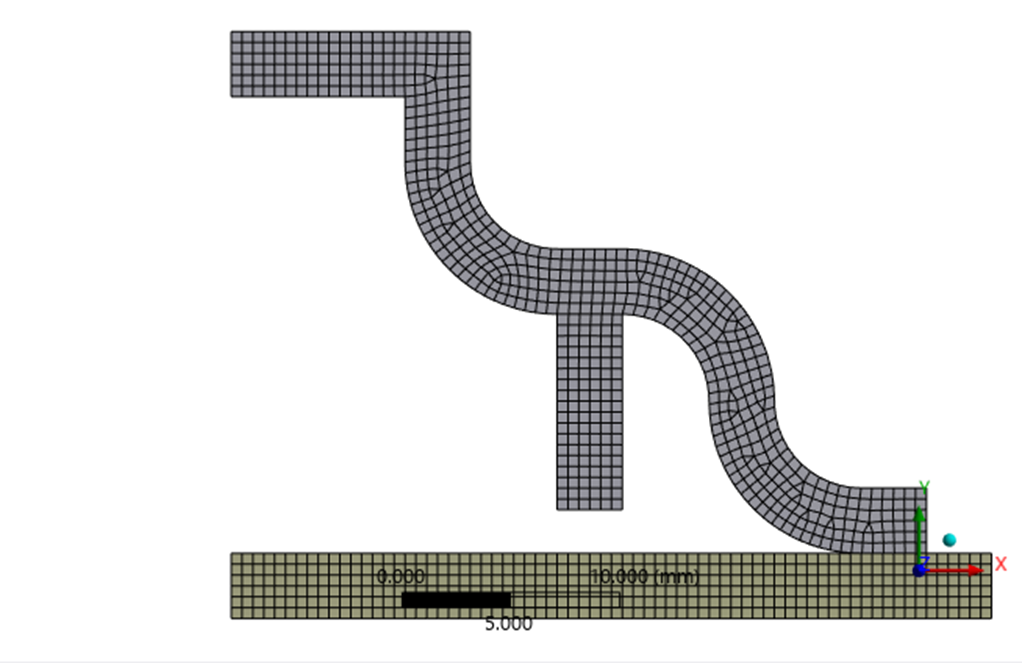
      Here is the undeformed mesh

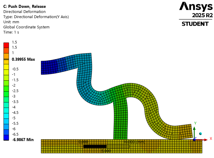
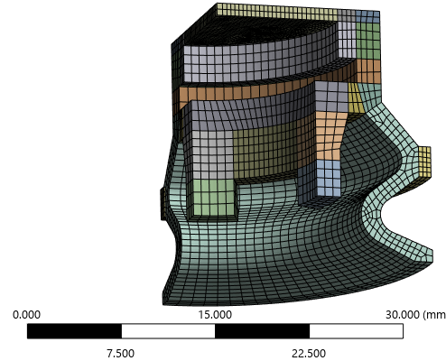
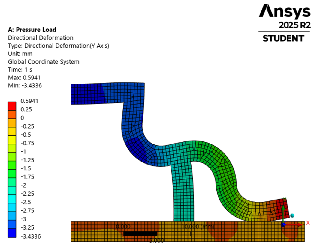
      Here is the deformation at step 1 with the negative surface pressure applied.

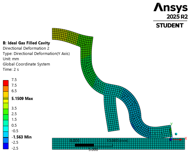
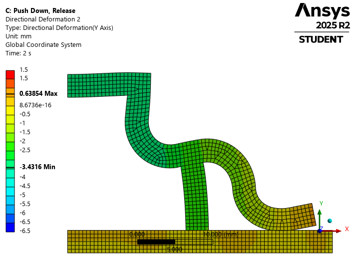
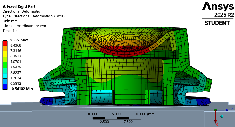
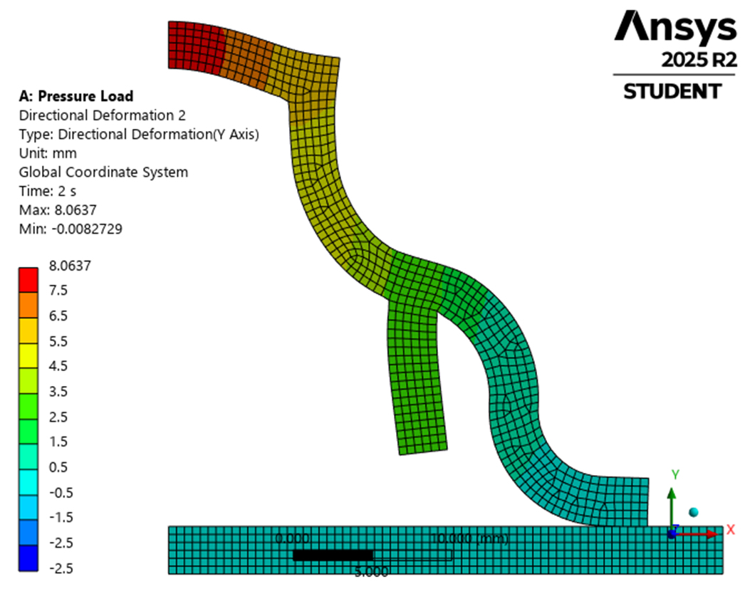
      Here is the step 2 deformation with the lift force applied.

      The second model has HSFLD241 fluid elements on the interior of the cavity formed by the cup and the base and uses the identical mesh, materials and loads.
      The deformation at step 1 is identical.

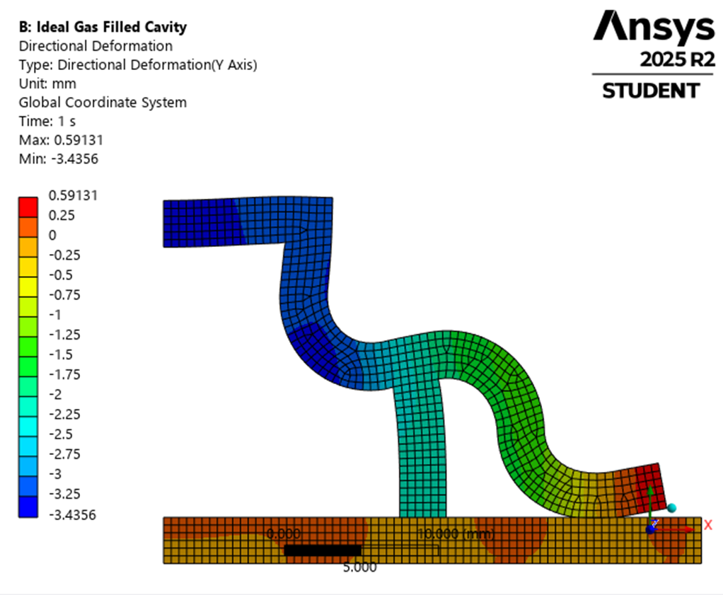
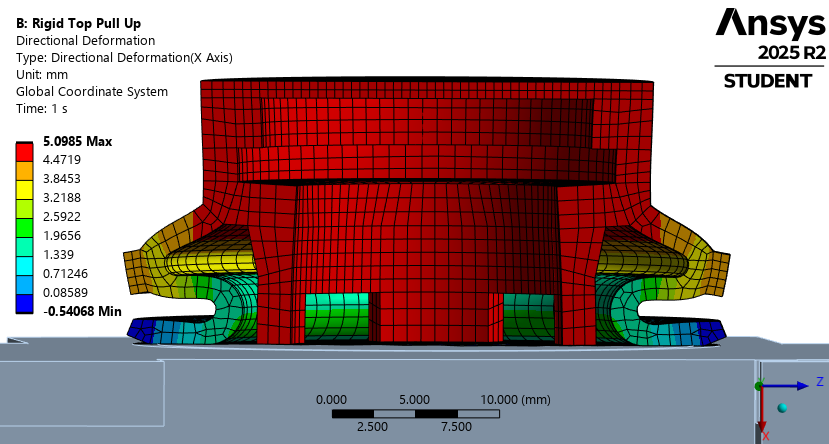
      The deformation at the end of step 2 when the force lifts the top of the cup is very different in this model than the first model.

      The dramatically different deformed shape between the second and first models when the top of the suction cup is lifted is because the air pressure in the cavity changes in this model!  The HSFLD elements couple the pressure in the cavity with the deformed shape of the cavity walls. In the first model, there is no coupling between the deformation and the pressure.  At the end of step 1, the vacuum pressure in the cavity for both models is -2.1E-2 MPa.  At the end of step 2 in the surface pressure model, the pressure didn’t change, but that does not correctly model the physics of the problem.  In reality, because there is a fixed mass of air under the cup at the end of step 1, trying to lift the top creates a higher vacuum pressure.  The air pressure at the end of step 2 is -6.2E-2 MPa in the model with the HSFLD elements compared with -2.1E-2 MPa in the surface pressure model.

    • peteroznewman
      Subscriber

      The above models provide a direct comparison between applying a negative surface pressure to the cup inside faces and pulling the same negative pressure on the air in the cup. While it’s possible to have a suction cup operate that way, it is more common to have a 3 step solution.  Step 1 has a downward force on the top of the cup, air escapes under the edge of the cup reducing the mass of air trapped under the cup.  Step 2 removes the downward force, the edge seals in the reduced air mass while the strain energy in the cup walls causes a vacuum pressure to form with that reduced air mass.  Finally in step 3, an upward force on the top of the cup can be applied which raises the vacuum pressure on the air mass a lot higher.

      Here is step 1 with a 20 N downward force where the HSFLD pressure node is held at 0 gauge pressure, simulating air escaping from under the cup as the top descends.

      Here is Step 2 where the top is released and has zero applied force.  The strain energy in the walls is released and causes a vacuum pressure of -1.95E-2 MPa in the air.

      In the last step, an upward force of 40 N is applied to the top of the cup and the vacuum pressure in the air increases to -5.11E-2 MPa.

    • b.mavroeidis2
      Subscriber


      Thank you very much for your help. I will provide the project link below. Just to clarify, the rotational velocity represents the rotation applied by the gripper, as seen in the photo below, and is not part of the issue I am investigating, so please disregard it. At this stage, I am reviewing the information already provided and gathering additional feedback before proceeding further.

      Thank you again for taking the time to look into this.

      https://drive.google.com/file/d/1ajq8nTFZ-YLFEs9Vcu1YLM_soGhX1HI2/view?usp=drive_link


    • peteroznewman
      Subscriber

      Thanks for the archive.

      Does the real suction cup have a tube connected to the flat top that provides a controlled vacuum pressure for the cavity?  This is common in material handling automation.  In that case, the model in my first example is the loading sequence to follow.  Or there is no tube and the suction cup relies on being squeezed down to expel some air to create the vacuum pressure in the cavity?  That loading sequence was shown in my second example.

      In my models, you can see I used six elements through the wall thickness of the suction cup. A section through your cup mesh is shown below and there is only one element through the wall thickness. This mesh is way too coarse for the analysis. A minimum of three elements is recommended. The last image shows something closer to what you need, but you can see it requires a lot of nodes and elements.


      If you take the time to slice the geometry into smaller pieces, you can obtain a more efficient hex mesh. This is a quarter model that would be mirrored to get the full cup.

      I recommend you watch this video to learn how to build a model with HSFLD elements.

       I plan to make a new video to explain how to model a suction cup based on my 2D axisymmetric models shown in my previous replies.

    • peteroznewman
      Subscriber

      Section view of a full 3D cup: Undeformed geometry

      HSFLD242 elements with a -1.5E-2 MPa pressure applied.

      Your archive had a pressure of -6.0E-2 MPa which seems excessive considering the large deformation of the top of the cup.

      However, I also noticed in your archive that the top of the cup had a Remote Displacement, Behavior = Rigid which would prevent this kind of deformation.

      Is the top face of the cup reinforced by other parts not shown? Does the real suction cup have a tube connected to the flat top that provides a controlled vacuum pressure for the cavity?

    • b.mavroeidis2
      Subscriber

      The top face of the cup is indeed reinforced by the mounting hardware it is attached to, which is why I assigned the Remote Displacement with Behavior = Rigid. The vacuum is supplied through a tube connected to the top of the cup, with a controlled vacuum level of approximately −(60-70) kPa. This value corresponds to the operating vacuum used by the real suction system. I have attached a photo of the actual suction cup.

    • peteroznewman
      Subscriber

      Thanks for the clarification. Here is the result with a rigid top.

    • b.mavroeidis2
      Subscriber

      Thank you for taking the time to run the model and share the results. The behavior looks much closer to what I would expect from the physical setup. If possible, would you be willing to share the Workbench project that produced this result?

    • peteroznewman
      Subscriber

      The model is not yet ready to share because it is only the first step in a multistep analysis and there are some problems to overcome getting steps 2 and beyond to run. I copied your figure from above and added a green dot with a white edge to indicate the pivot point of the arm that supports the pipe that has the suction cup at the end that holds the object.

      Can you provide the global coordinates of the center of the green dot that is the axis for the pivot?  Or if you include the pipe, arm and pivot in the CAD, I can turn those into rigid bodies and simply put a Revolute Joint on the Pin and add a Joint Load to rotate the joint.

      I see you had a rotational velocity in your model of 1.57 rad/s but a more realistic load is the rotational acceleration profile of that revolute joint. The angular acceleration ramp up to that peak velocity may generate higher forces on the mass of the object held by the suction cup than a constant angular velocity with zero angular acceleration.

      Can you provide the angular acceleration profile of the arm at that pivot?

    • b.mavroeidis2
      Subscriber

      At this stage, a specific rotation path is not required. For the next steps, let's assume the suction cup is mounted to a pivot located 50 mm from the back face of the cup (pivot-to-cup center distance = 50 mm). The exact global coordinates of the pivot are therefore not critical.

      I do not currently have a measured angular acceleration profile for the real system. However, a representative motion is a 90° rotation completed in approximately 1 second. A reasonable assumption would be a motion profile with relatively high initial angular acceleration, followed by a period of approximately constant angular velocity, and then an aggressive hard-stop approaching the final 90° position. 

Viewing 11 reply threads
  • You must be logged in to reply to this topic.
[bingo_chatbox]