-
-
May 15, 2020 at 5:23 am
iris
SubscriberÂ
 Somebody could help me?
 I am using desing HFSS (DrivenModal), a primitive PolygonHelix to design a flat coil, using the basic standards of antenna design. I use a triangle as an excitation port (Lumped port). I also create a radiation box, a setup (560 hz) and an analysis frequency. I simulated the coil with 10 turns, although I would like to vary the number of turns later, however when compiling it works well but when analyzing everything, the answer is as shown in the images. Any suggestion.
Â
-
May 18, 2020 at 7:37 pm
iris
Subscriber
Â
Hola Iris,
Â
Soy Samuel, ingeniero de Ansys en la parte de alta frecuencia. Voy a intentar ayudarte con tu problema.
Â
Por tu descripción es difÃcil conocer la raÃz del problema. ¿PodrÃas dar más detalles sobre la geometrÃa? O incluso ¿podrÃas adjuntar una imagen de la antena y el Setup que están realizando.
Â
Supongo que tendrás experiencia con HFSS, pero las 'normas' básicas de cualquier simulación de antenas es:
Â
1) Tener al menos un puerto de excitación (Waveport o Lumped Port, dependiendo de como sea tu antena)
Â
2) Definir una 'Radiatio Box'. Si vas al Project Manager, y haces click derecho sobre 'Model' verás la opción 'Create Region'. Después podrás generar 3 tipos de región de radiación, para comenzar te recomiendo 'Radiation' y la frecuencia de funcionamiento de tu antena.
Â
3) Por úttimo definir el Setup (frecuencia a la que tu antena funciona) y el Sweep de frecuencia que quieras analizar.
Â
Si me das más detalles de la antena podré ayudarte. Una última consideración, para próximas dudas es más conveniente que escribas tus dudas en inglés, asà podremos ayudarte mejor y de forma más eficiente.
Â
Muchas gracias,
Samuel
-
May 19, 2020 at 6:21 am
Samuel Lopez
Ansys EmployeeÂ
Hi Iris,
Â
It is not clear how you are implementing the ports, I guess, it is where you have the issue.
Â
In all HF Simulation Softwares as HFSS you need to define the Ports in a consistent way, I mean, they always must connect the Active part to the Ground. In the Coil case, you have to 'end parts', and you should connect both.
Â
In the following case you can see what I meant:
Â
Â
Â
Â
As you can see, the 2 ended parts are connected with a metal plate and the corresponded ports:
Â
Â
Â
Â
If you want an antenna with only 1 port, you can perform the following Setup:
Â
Â
As you can see a metallic trace has been created from the inner part to the bottom part, after this you can connect with one port the inner to the outer coil.
Â
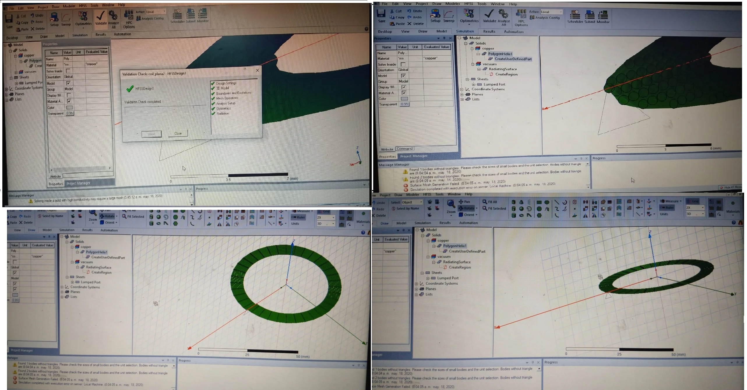
This would be the most efficient setup for a coil, once you have it, please check if HFSS performs correctly the Mesh. As HFSS Users we have to know how the antenna is modelled and created in real life to perform the most accurate model (materials, how the antenna is excited...). HFSS then will obtain the most accurate result.
Â
Please let me know if it helps you.
Â
Thanks,
Â
Samuel
Â
Viewing 2 reply threads- The topic ‘Simulation completed with execution error on server: Local Machine.’ is closed to new replies.
-
- Y wiring method and the start and end points of winding.
- Lumped Port Deembed
- Optimizing Via Impedance in Ansys HFSS 3D Layout Using Geometric Parameter Sweep
- HFSS libnvidia-ml.so too old or could not be found – Warning in slurm job output
- Hfss 3D pcb via capped and filled with epoxy
- AEDT Natural Convection with default correlation is failing solver initializatio
- Three-Phase Voltage Imbalances in dual stator electric generator
- STL Import Errors in HFSS After Cleaning in SpaceClaim
- Calc Error in Field Calculator after PyAEDT Analyze
- import file autocad 3d
-
3912
-
1414
-
1256
-
1118
-
1015
© 2025 Copyright ANSYS, Inc. All rights reserved.