TAGGED: interconnect, photonics
-
-
July 24, 2023 at 1:24 pm
Aneek James
SubscriberHello all,
Is there a way to change interconnects settings such that more than 2 orthognal modes are supported at any given time? It seems like it default assumes you'd only be interested in a TE and TM like mode, but what if you wanted to simulate more than just these two? When I load an s parameter file (generated from an FDTD sim) with 3 modes defined, the ONA element only shows the results for the first two modes, but not the last one.
Thanks!
-
July 26, 2023 at 10:30 pm
Devika Padmakumar Nair
Ansys EmployeeHello,
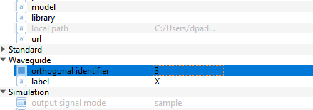
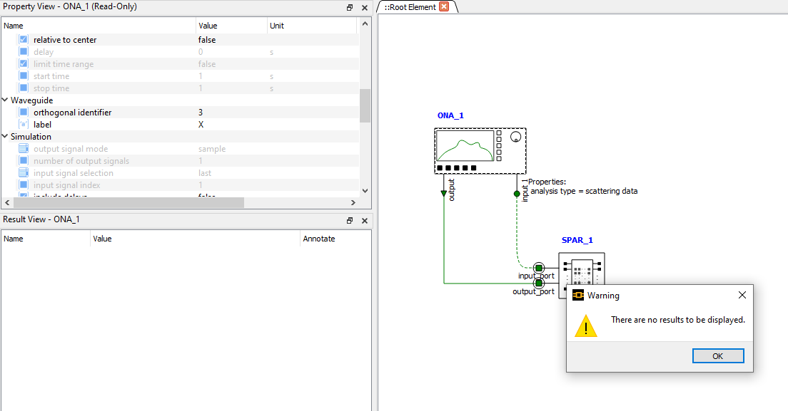
ONA will show results for the mode corresponding to the orthogonal identifier. If you like to visualize mode 3, change the value to 3 and run the simulation.
You can find more information on ONA here : Optical Network Analyzer (ONA) - INTERCONNECT Element – Ansys Optics
Thank you.
-
July 27, 2023 at 3:44 pm
-
-
July 27, 2023 at 3:54 pm
Devika Padmakumar Nair
Ansys EmployeeThis seems like no mode 3 data in S-parameter file. I tried with my simulation and I am getting result. Can you doble check S-parameter file?
-
July 27, 2023 at 3:57 pm
Aneek James
SubscriberThe .dat file was generated from an S-parameter sweep, so it should be formatted correctly. I'm checking and there's data for each port and mode as expected. The data in the file also matches the data I saw in the vizualizer in FDTD.
I can't upload the file for CUI reasons, but can you upload the .dat file that you're using? So I can compare what's different?
-
July 27, 2023 at 4:03 pm
Devika Padmakumar Nair
Ansys EmployeeWe cannot download any file. But I can definitely try simulating a similar device and test. Which component are you using to generate S-parameters? Please let me know.
-
July 27, 2023 at 4:06 pm
Aneek James
SubscriberI don't think I can mention what device it is, but showing me how this would work for a multi-mode waveguide that supports 3 modes would help.
-
July 27, 2023 at 10:03 pm
-
- The topic ‘Simulating More than Two Orthogonal Modes in INTERCONNECT’ is closed to new replies.


-
3477
-
1057
-
1051
-
945
-
912

© 2025 Copyright ANSYS, Inc. All rights reserved.


