-
-
October 16, 2023 at 6:55 am
Amogh G
SubscriberHello,Â
I've been trying to simulate a metagrating unit cell. The structure consists of microstrip capacitors printed on a substrate backed by a PEC according to the existing literature, as shown below.
To simulate an infinite array environment, coupled primary-secondary boundary conditions are imposed on XZ and YZ planes of the radiation box. The XY plane (top face) is assigned as floquet port as shown below.
The structure has been designed to anomalously reflect the normally incident, TE polarized wave to 60 degrees. I am unable to analyze the functionality by plotting the electric fields and radiation pattern. The radiation pattern obtained is peculiar and am not to able comprehend the same.Â
It would be helpful if any guidance could be provided on appropriate simulation and analysis procedures.Â
Thank you
Regards,
Amogh G
amoghg.ec20@rvce.edu.in
-
October 19, 2023 at 2:04 am
Faezeh Ladani
Ansys EmployeeHi Amogh,Â
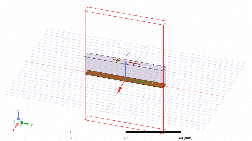
Note that coupled primary/seconary boundary are set for a specific scan angle. So, they cannot support incidence at normal for a reflection at 60deg simultanously. Best is to create a larger number of the capacitors by duplicating and simulate an explicit array inside a PML boundary.
You may start from a few elements and then increase the elemenst in a few steps to kind of extrapolate the results for huge/infinite array.Â
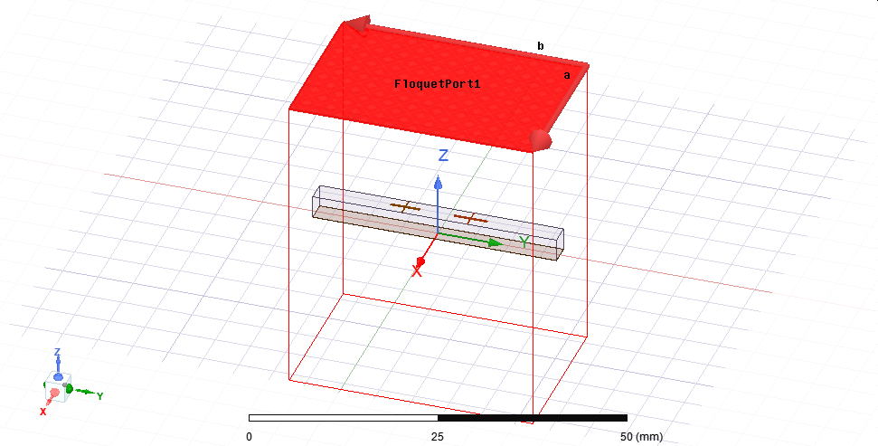
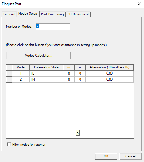
Also, regardless of this situation, when using unit cell simulation make sure you use enough number of modes for floquet port (using mode calculator). You can read more about it in HFSS online help.Â
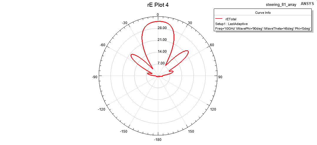
Another aspect of unit cell simulation is that far field pattern is not simply done as regular antenna problems. You need to create embedded element pattern by doing a parametric simulation for each scan angle and read only one point of far field along the scan angle. Again, not related here, just FYI.Â
-
November 9, 2023 at 5:58 am
Amogh G
SubscriberÂ
Hello,
Thank you for your response. Considering your suggestions, we have simulated the structure. We are now unable to use the field calculator to obtain the x- component of the electric field in the plane. We want to plot the magnitude of the real part of the x polarised field. We are using the field calculator instead of the field overlays option as it could potentially provide individual componets of the field unlike the one in the field overlays that provides us with all the components.Â
Â
-
November 16, 2023 at 10:56 am
Amogh G
SubscriberHello,
I hope my query has been delivered to you. We would appreciate your timely response to our queries. Thank you.
-
- The topic ‘Simulating Metagrating (Meta-atoms) unit cells with Floquet excitations’ is closed to new replies.
-
3487
-
1057
-
1051
-
955
-
922
© 2025 Copyright ANSYS, Inc. All rights reserved.