TAGGED: shock, shock-analsysis, srs
-
-
October 1, 2024 at 10:01 am
jerome.chassin
SubscriberHello all,
I recently get interrested in SRS (Shock response spectrum). The theory I understood here is to idealize the system as a 1D mass/spring/damped system.
I tried to recreate a simple system with a bushing and a point mass ( I fixed the stiffness of the bushing, I am changing the mass in order to change de natural frequency, Damping numerical=0.005)
Shock impulse is an Half sine curve (Amplitude 3g, duration 30ms)
Boundary condition, the system is in 1D( All displacement blocked but the vertical direction)
Transient simulation data: Duration 0.5s, time step 0.001s, numerical damping (default=0.005)
Here are the results given :
I found in the litterature the following curve that I should have:
My problem is that I don't have at all the same result, the higher is the natural frequency the lower is the response going to an asymptote close to 0 instead of 1.Do you know what I am missing here?
My guess is that it is link to the numerical damping effect:
I think I should open a new dicussion about this following topic but I think it is somehow linked.We usualy perform a half sine pulse to a complexe system. In theory the severity of a shock is the velocity change (Energy in the system= 1/2mv^2).Meaning that a 3g 30ms should be equivalent to a 1.5g 60ms shock, but if I compare the maximum stress of the 2 simulations I dont have at all the same result . Any idea why? ( for me it is driven directly from the amplitude of the shock acceleration, in other hand I understand that the severity of a shock is driven from the velocity)
Thanks for your help :)
-
October 3, 2024 at 11:21 am
jerome.chassin
SubscriberSmall edit on this topic.
Looks like results were relative and not absolut while the graphic from the paper is in absolut.
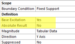
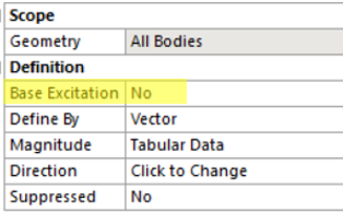
By changing the options of the shock param I have different results and tested differents configurations:
config A:
config B:
Config C:
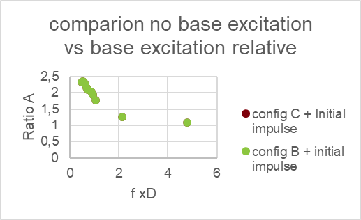
I have the following results:
What I understand from this is Config B and C are equivalent, while Config A have a significant impact on the system.
I initially thought that results would be equivalent and it would be only a visualisation matter, but it don't seems to be the case. This arise a new question, what would be the correct methology to simulate a shock that is meant to be on a test table? Looks like the correct way would be to simulate by displacement as configuration A which is much more complexe, time consuming, and poor visualization.(giving a a half sinus pulse acceleration results to infinite displacement.
Thanks for your feed back.
-
October 4, 2024 at 1:58 pm
dlooman
Ansys EmployeeI think you have pretty much answered your own questions. There are two ways to solve for the half sine acceleration pulse. Constrain the base and apply the acceleration as a body load (my preferred method, but the results are relative to the base) and the Base Excitation method in which the acceleration is applied as an actual displacement at the base. The 2nd method has the advantage of producing the absolute acceleration, but has the disadvantage of producing a non-zero velocity at the end of the half sine pulse (integral of the sine pulse acceleration) and a large amount of rigid body motion if the transient is continued for some time. In a real model it can also introduce issue of correct time-stepping. I don't think time-integration equation will significantly affect your results, but you can set it manually to a small number. It produces a sort of numerical damping equal to (time integration contant)/2pi. Damping is only significant when you have a steady state sinusoidal load at the resonant frequency.
-
October 4, 2024 at 3:49 pm
jerome.chassin
SubscriberThanks for your answer.
I get that the non 0 velocity is a problem, I am thinking to apply a pre pulse and post pulse to solve this issue and have 0 acceleration, velocity, displacement at the end and begining of the simulation as for the real test on a table ( the input of the simulation would then be displacement.).
-
October 4, 2024 at 4:17 pm
dlooman
Ansys EmployeeI think the acceleration will need to have be a cosine function from 0 to 2pi.
-
- You must be logged in to reply to this topic.


-
3367
-
1050
-
1047
-
886
-
837

© 2025 Copyright ANSYS, Inc. All rights reserved.


