
TAGGED: joint
-
-
January 11, 2021 at 9:23 am
Ing_F
SubscriberHi,
I'm writing my master thesis and i have to study the behavior of a structure. The company guidelines are to use the midsurface command for the beam and solid for the support. Currently, I've imprinted the profile of the beam on the solid and I've connected them with fixed joint. I know there are problems with this since the different DOF, any suggestion?
January 11, 2021 at 1:40 pmpeteroznewman
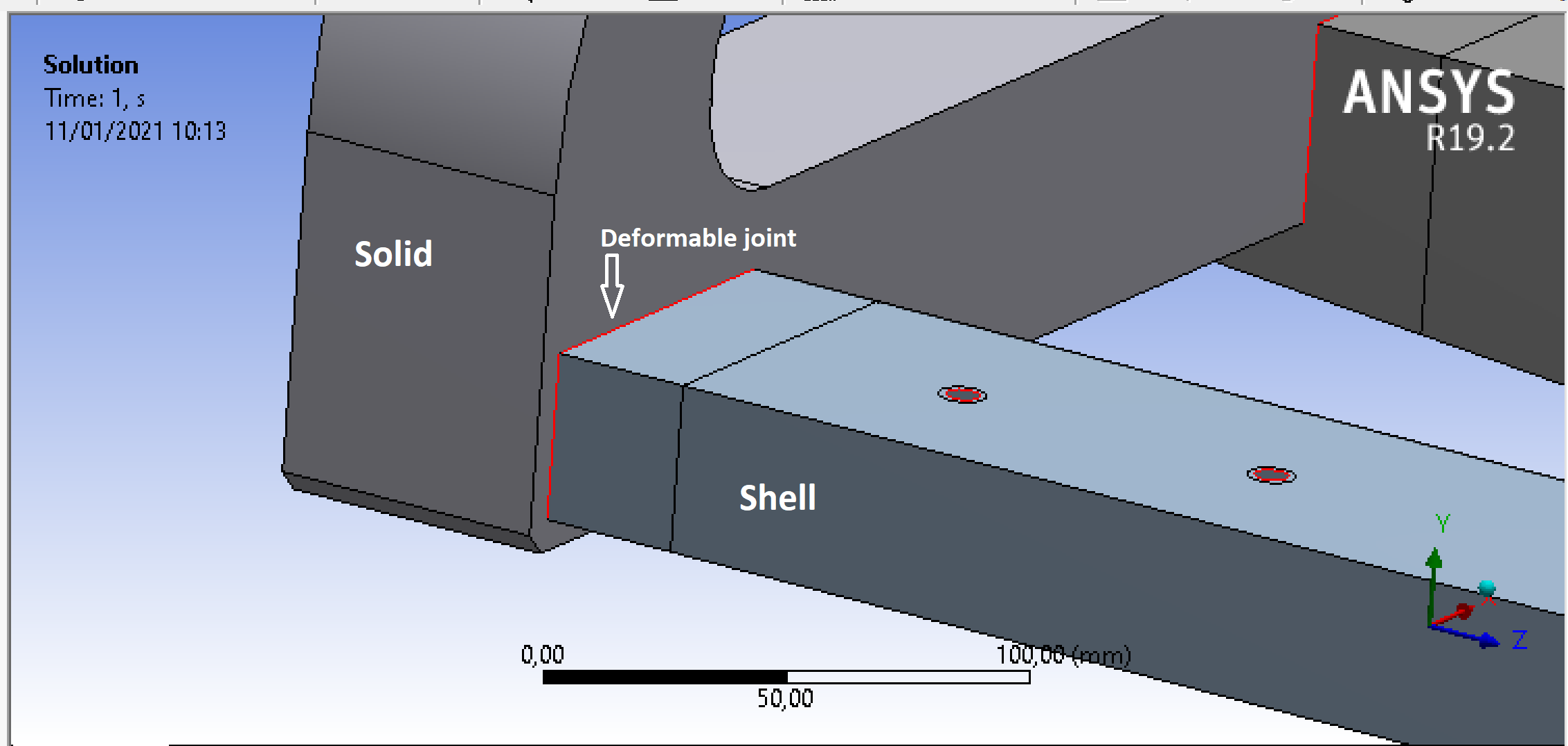
SubscribernIn the image above, it looks like the shell elements are on a C-channel or rectangular tube.nAn example of the DOF problem arises when the nodes along one straight line at the end of a shell body are merged with a coincident line of nodes on solid elements on the adjacent body. This creates a hinge.nYou have imprinted three (or four) lines on the solid elements, and that can support moments where one line cannot. The Fixed joint will work as intended.nnJanuary 11, 2021 at 2:08 pmSubscriberThanks peter I was hoping you would answer. It's a rectangular tube.n
 So use a deformable joint makes sense? Could I consider the results reliable? Here I connected edge to edge, so 4 joint but I could do the same with one joint (4 edge to 4 edge) and the result are very different.nnHere the image of MPC connections and the resultn
January 12, 2021 at 4:26 amSubscribernBlack text on a dark blue background is difficult to read. There is a Semi-Transparent setting on the Legend or I prefer to change the dark blue color to light grey.nLet's assume that there is a full length, full penetration fillet weld fastening the tube to the frame. There are lots of ways to connect the shell elements on the tube midsurface to the solid elements on the end frame. nBonded Contact. nI would choose this since there is automation built in to Workbench to find edges on faces and automatically create the contact. This is really good if you have dozens of tube ends to weld to frames. I would set the contact to MPC because I like to see the spider elements to see how far from edge the spider went, and that distance can be controlled by the Pinball radius. You can also drag and drop all the bonded contacts onto the mesh to refine the mesh at the contacts, more nice automation.nSingle Rigid JointnOne benefit of a single rigid joint is you can Probe the Total Force going through the joint, which can be useful to know if you want to do a simple hand calculation on the nominal stress in the weld fillets. I think a Rigid joint is more realistic than Deformable in this example because the flat frame surface causes the rectangular tube section to remain rectangular, which is what the Rigid setting does. The Deformable setting allows the rectangular cross-section at the end to deform which can't happen in this example.nFour or more JointsnAllows more accuracy in the weld stress by Probing the Force components going through each edge. Maybe the weld drawing shows 5 mm long stitch welds. Now you can get a very high fidelity weld stress calculation by putting 3 and 5 joints along each edge and the Force going through each weld segment can be obtained individually. One of them is going to carry the highest force. With multiple joints, you can make them Deformable because no single joint is trying to maintain the rectangular cross-section, they do that as a group.nANSYS 2020 R2 has introduced some new software that makes defining welds even better.nViewing 3 reply threads
So use a deformable joint makes sense? Could I consider the results reliable? Here I connected edge to edge, so 4 joint but I could do the same with one joint (4 edge to 4 edge) and the result are very different.nnHere the image of MPC connections and the resultn
January 12, 2021 at 4:26 amSubscribernBlack text on a dark blue background is difficult to read. There is a Semi-Transparent setting on the Legend or I prefer to change the dark blue color to light grey.nLet's assume that there is a full length, full penetration fillet weld fastening the tube to the frame. There are lots of ways to connect the shell elements on the tube midsurface to the solid elements on the end frame. nBonded Contact. nI would choose this since there is automation built in to Workbench to find edges on faces and automatically create the contact. This is really good if you have dozens of tube ends to weld to frames. I would set the contact to MPC because I like to see the spider elements to see how far from edge the spider went, and that distance can be controlled by the Pinball radius. You can also drag and drop all the bonded contacts onto the mesh to refine the mesh at the contacts, more nice automation.nSingle Rigid JointnOne benefit of a single rigid joint is you can Probe the Total Force going through the joint, which can be useful to know if you want to do a simple hand calculation on the nominal stress in the weld fillets. I think a Rigid joint is more realistic than Deformable in this example because the flat frame surface causes the rectangular tube section to remain rectangular, which is what the Rigid setting does. The Deformable setting allows the rectangular cross-section at the end to deform which can't happen in this example.nFour or more JointsnAllows more accuracy in the weld stress by Probing the Force components going through each edge. Maybe the weld drawing shows 5 mm long stitch welds. Now you can get a very high fidelity weld stress calculation by putting 3 and 5 joints along each edge and the Force going through each weld segment can be obtained individually. One of them is going to carry the highest force. With multiple joints, you can make them Deformable because no single joint is trying to maintain the rectangular cross-section, they do that as a group.nANSYS 2020 R2 has introduced some new software that makes defining welds even better.nViewing 3 reply threads- The topic ‘Sheel and solid connection’ is closed to new replies.
Innovation Space Trending discussions
 Top Contributors
-
peteroznewman
 6379
6379 -
scabo
 1906
1906 -
Dennis Chen
 1457
1457 -
javat33489
 1308
1308 -
Shyam Prasad V Atri
1022
Top Rated Tags
© 2026 Copyright ANSYS, Inc. All rights reserved.
Ansys does not support the usage of unauthorized Ansys software. Please visit www.ansys.com to obtain an official distribution.
-


The Ansys Learning Forum is a public forum. You are prohibited from providing (i) information that is confidential to You, your employer, or any third party, (ii) Personal Data or individually identifiable health information, (iii) any information that is U.S. Government Classified, Controlled Unclassified Information, International Traffic in Arms Regulators (ITAR) or Export Administration Regulators (EAR) controlled or otherwise have been determined by the United States Government or by a foreign government to require protection against unauthorized disclosure for reasons of national security, or (iv) topics or information restricted by the People's Republic of China data protection and privacy laws.
