
TAGGED: nonlinear-buckling
-
-
December 10, 2021 at 5:39 am
gfeng01
SubscriberHi,
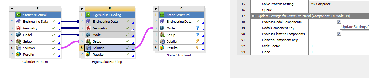
I'm trying to make a nonlinear buckling analysis based on the model built for linear buckling. I'm told that scale factor would significantly affect the accuracy of the result in nonlinear analysis, but I don't know the definition of it. Could anybody tell me how to specify the value of scale factor?
December 10, 2021 at 8:02 amErKo
Ansys EmployeeHi
So say we have 10 mm movement say in x at the top of the structure then when we use a scale factor of 1 the mesh node there of the deformed configuration in the static system (system G say) will have moved and will be 10 mm in X relative the unreformed configuration (system E).
Thus it is up to the user to provide a scaling factor that they are happy with. Ansys does not have a built in value (hence why we can enter whatever we like - it is user defined), so again it is as you can see up to the user to define that as they want.
All the best
Erik
December 10, 2021 at 5:01 pmSubscriber
Thanks for your answer! I wonder if the scale factor would have any impact on the result of deformation? Or it just changes the effect of visualization?
Regards Guodong
December 10, 2021 at 5:47 pmAnsys EmployeeHi
As we said the scale factor as you use it will generate a deformed imperfect geometry, so it really changes your geometry in system G (it is a deformed geometry) so if you have a half sine as buckling mode for a simple beam, then your geometry will be depending the scale factor like a half sine shape beam - try that and you will see in your static system (G) that the geometry follows the shape of your buckling mode, which is the first one in your screenshot. The higher the scale factor the more deformed the geometry will be. The user as we say needs to define how much we deform and make an imperfect geometry.
I will leave that with you. All the best.
Erik
Viewing 3 reply threads- The topic ‘Scale Factor of Buckling Analysis’ is closed to new replies.
Innovation Space Trending discussions
 Top Contributors
-
peteroznewman
 6495
6495 -
scabo
 1906
1906 -
Dennis Chen
 1458
1458 -
javat33489
 1308
1308 -
Shyam Prasad V Atri
1022
Top Rated Tags
© 2026 Copyright ANSYS, Inc. All rights reserved.
Ansys does not support the usage of unauthorized Ansys software. Please visit www.ansys.com to obtain an official distribution.
-


The Ansys Learning Forum is a public forum. You are prohibited from providing (i) information that is confidential to You, your employer, or any third party, (ii) Personal Data or individually identifiable health information, (iii) any information that is U.S. Government Classified, Controlled Unclassified Information, International Traffic in Arms Regulators (ITAR) or Export Administration Regulators (EAR) controlled or otherwise have been determined by the United States Government or by a foreign government to require protection against unauthorized disclosure for reasons of national security, or (iv) topics or information restricted by the People's Republic of China data protection and privacy laws.
