TAGGED: hfss, photonics, s-parameters
-
-
July 15, 2021 at 11:30 am
djihad-amina.djemmah
SubscriberHello,
I have a question about the relative error.
I wanted to know how to decrease the relative error on the values of S11 and S21 (I am usinig grating S parameters).
With HFSS software we have Delta S, does lumerical have something similar?
If not, how can we get the precise values of S?
Thank you in advance.
July 15, 2021 at 6:05 pmGuilin Sun
Ansys EmployeeHFSS is our sister software which uses finite element method in frequency domain. I am not very sure for HFSS, but it seems when it adaptively refines its meshing, the result will change and thus s can be averaged and get delta_s. However, FDTD updates iteratively the EH fields in time steps on the determined spatial mesh, it has fixed result. If Delta-S is resulting from different mesh size, you can do this by use of different mesh size/mesh accuracy, which Lumerical calls this as converging test. Convergence testing process for FDTD simulations
So the accuracy of S depends on several factors in FDTD, with dominant factor of mesh size while all other settings are properly set.
August 9, 2021 at 7:45 amdjihad-amina.djemmah
SubscriberHello Thank you for your answer.
I will try to be more precise in my question.
I am simulating a 2D structure and I need to retrieve the S parameters in order to extract the effective parameters (refractive index, impedance, permittivity and permeability).
The problem I encounter when I extract the effective parameters, peaks without physical meaning appear on the impedance curve, these peaks appear when S21^2 is close to unity while S11 is close to 0.
To solve this problem with HFSS it is sufficient to decrease the delta S.
P.S HFSS uses the finite element method. It creates a mesh and then the process continues to calculate different parameters such as the diffusion parameter, vswr, etc. The difference between each pass is the delta S. To get maximum accuracy, we can decrease the delta S.
With lumerical, I tried to vary the mesh size/mesh accuracy as well as the simulation time but I could not solve the problem.
Looking forward to your answer.
August 9, 2021 at 3:49 pmGuilin Sun
Ansys EmployeeAs mentioned previously, FDTD gives result at a fixed mesh. So to solve the issues you are facing, you may try two different methods:
1: if it is due to inaccurate S, you can improve the simulation accuracy by doing converging test. Please refer https://support.lumerical.com/hc/en-us/articles/360034915833-Convergence-testing-process-for-FDTD-simulations
2: if it is cause by S12 ~1 and S11~0, it is due to the mathematic operation with complex numbers. You can re-arrange the operation, for example using S=abs(S)*exp(1i*phase), or manually make the denumerator real etc. you May need to plot all the intermediate parameters and try to find the cause, eg, plot (1+S11)^2-S21^2 and (1-S11)^2+S21^2.
Most likely it is due to the math operation. Please try to use different methods. You may also try to use other software such as matlab.
August 9, 2021 at 4:01 pmdjihad-amina.djemmah
SubscriberI'm coming back to you because I've been trying to solve this problem for almost a month and I can't, and unfortunately my work is not progressing because of this.
I have varied the number of PML layers, the mesh precision, the mesh size and the simulation time.
I managed to reduce the size of the peaks but it is not enough to make them disappear.
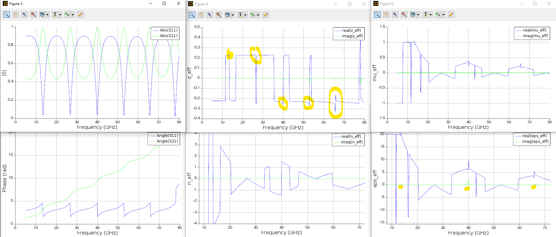
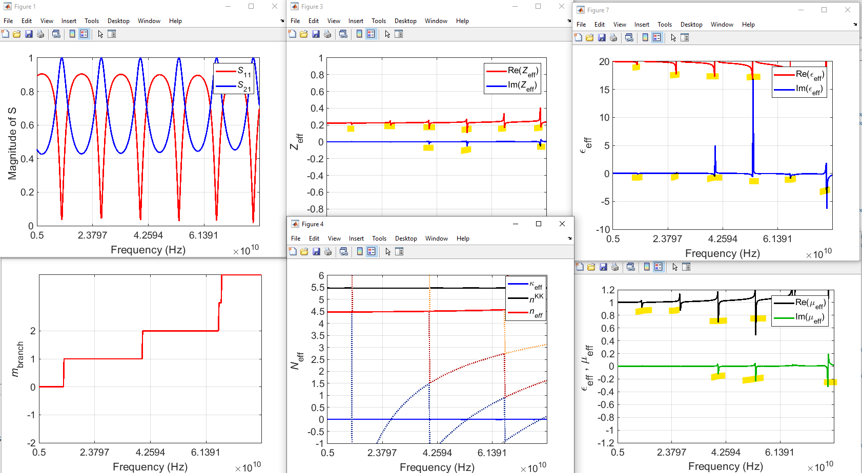
I used two extraction methods: Smith's method (fig 3) and Szabo's method (fig 4) with both methods we can see that the peaks which they don't have any physically significant.
With the Smith model, there is also a fluctuation problem as you can see in fig 4(I don't know why they appear) .


I'm getting desperate, please help me.
Waiting for your reply
August 9, 2021 at 4:22 pmGuilin Sun
Ansys EmployeeI think you have duplicated your question in other post: S parameters Please do not duplicate it since this is a waste of resources.
From your result, it is clear that the frequency range is too wide that the phase change of S parameters is larger than 2pi. I believe that it is this issue that causes problem. This is the math issue not simulation issue. One simple way is to simulate different frequency range with phase change less than 2Pi. However this may create other issues such as the result is not continuous. I still suggest that you plot the two intermediate quantities and see if they are continuous, and then try to improve the result by all means.
From my experience, sometimes even the two intermediate quantities are continuous, how to calculate the square-root also may lead to different result. This may be script-dependent, eg, different program language could lead two different results but mathematically they are correct. This is mainly due to the branches of the complex square-root operation.
Viewing 5 reply threads- The topic ‘S parameters’ is closed to new replies.
Innovation SpaceTrending discussionsTop Contributors-
5649
-
1885
-
1404
-
1303
-
1021
Top Rated Tags© 2026 Copyright ANSYS, Inc. All rights reserved.
Ansys does not support the usage of unauthorized Ansys software. Please visit www.ansys.com to obtain an official distribution.
-