Hi again, these were the errors and warnings I received:
The solution was executed using restart information
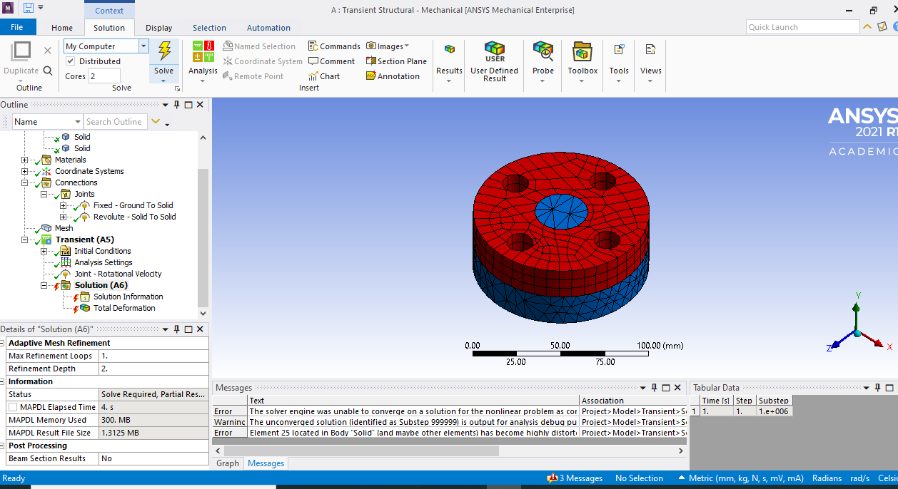
The solver engine was unable to converge on a solution for the nonlinear problem as constrained.Please see the Troubleshooting section of the Help System for more information.
The solution failed to solve completely at all time points. Restart points are available to continue the analysis.
Although the solution failed to solve completely at all time points, partial results at some points have been able to be solved.Refer to Troubleshooting in the Help System for more details.
The unconverged solution (identified as Substep 999999) is output for analysis debug purposes. Results at this time should not be used for any other purpose.
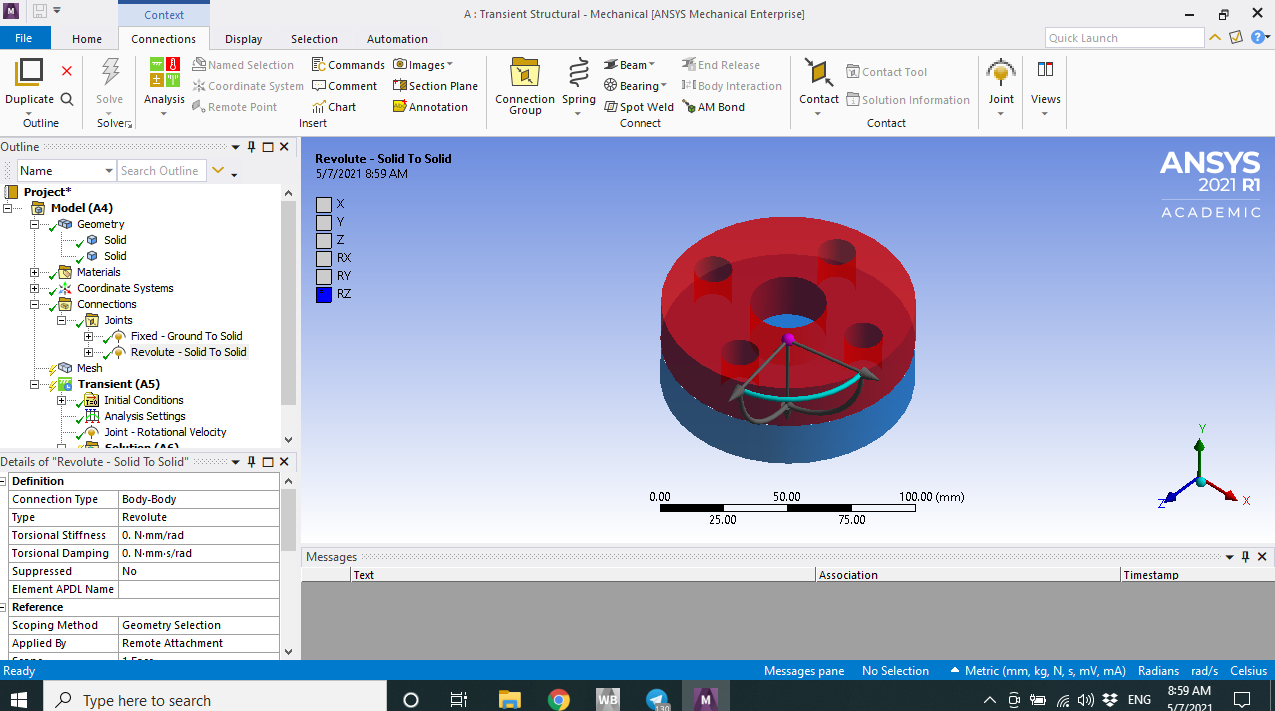
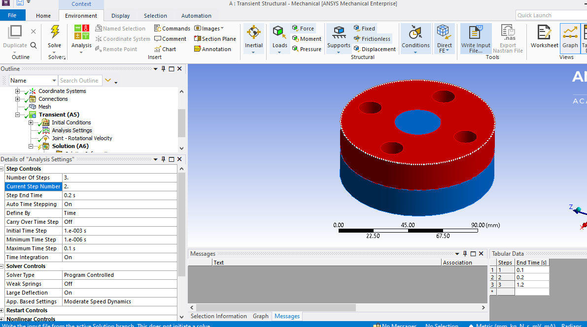
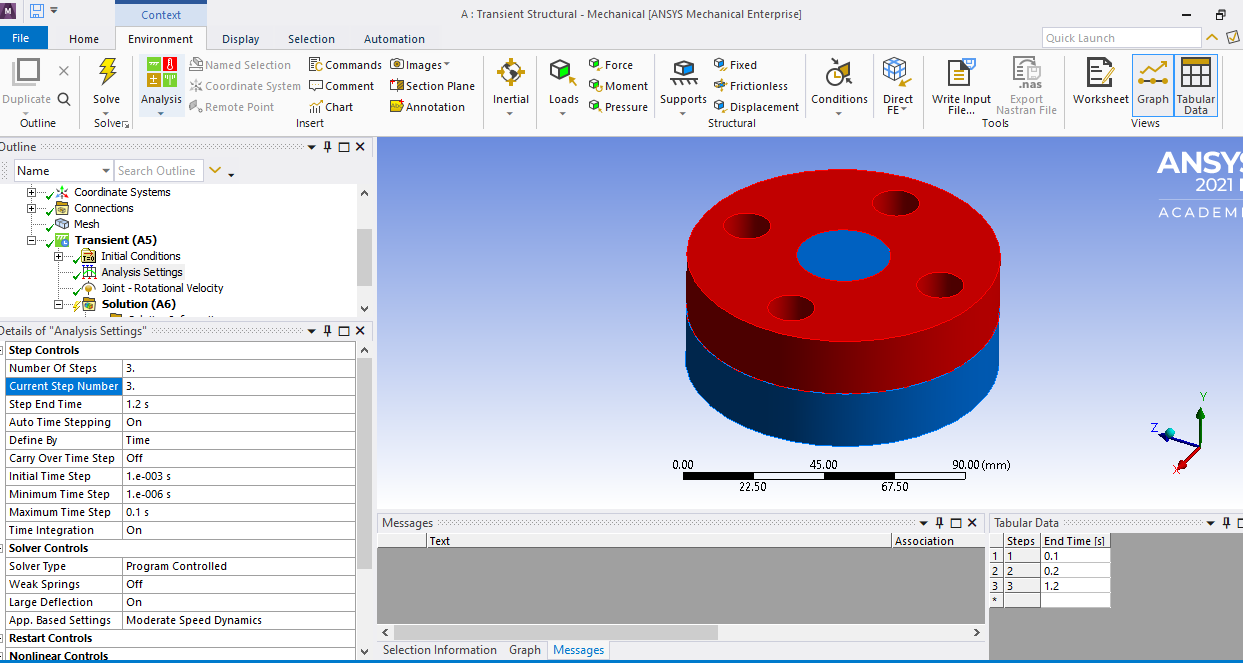
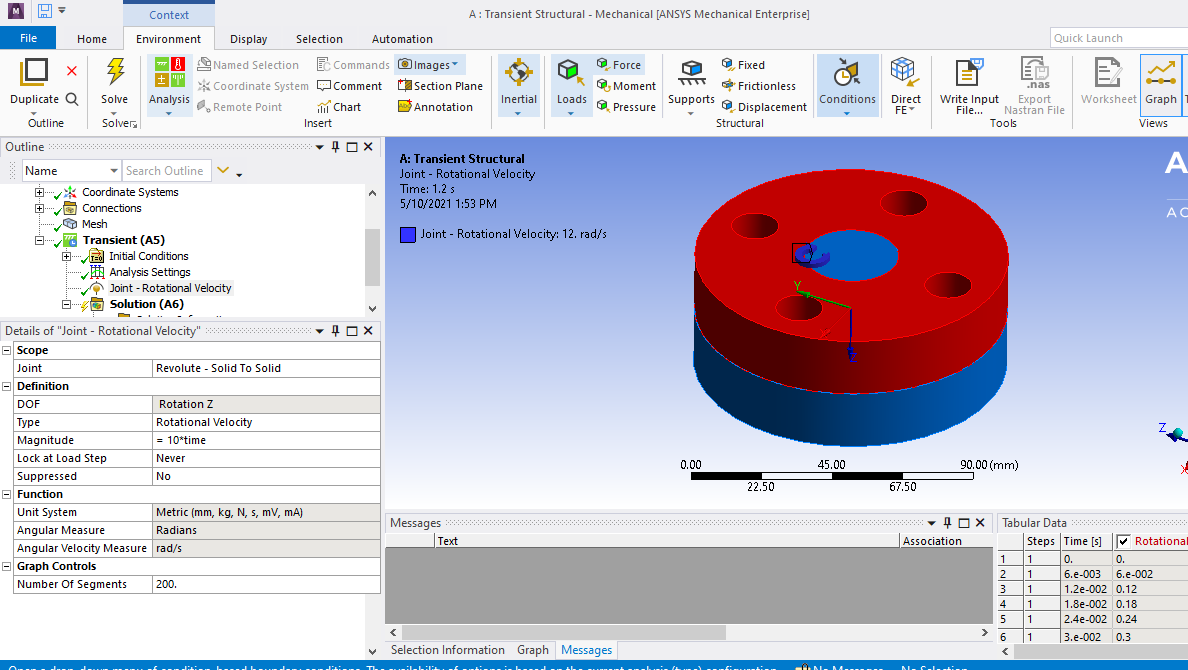
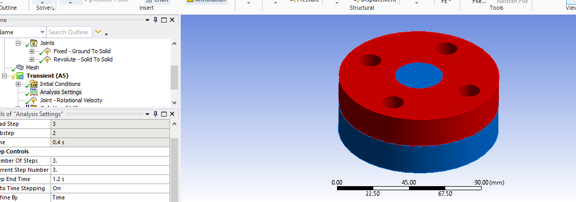
Here you see the model:
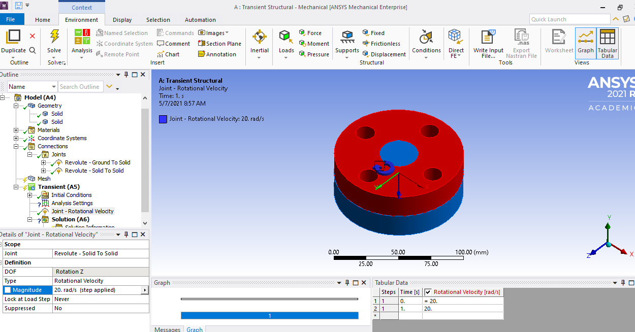
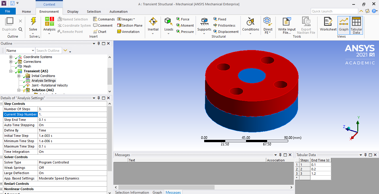
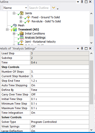
The analysis setting is here:
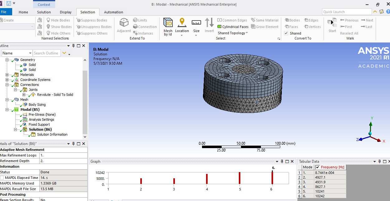
The force convergence plot could not be obtained because the Ansys cannot solve the current situation. To my odds, the same settings in a rigid dynamics environment give me results.