TAGGED: wrong-modes
-
-
August 12, 2024 at 2:12 pm
Fakhriyya Mammadova
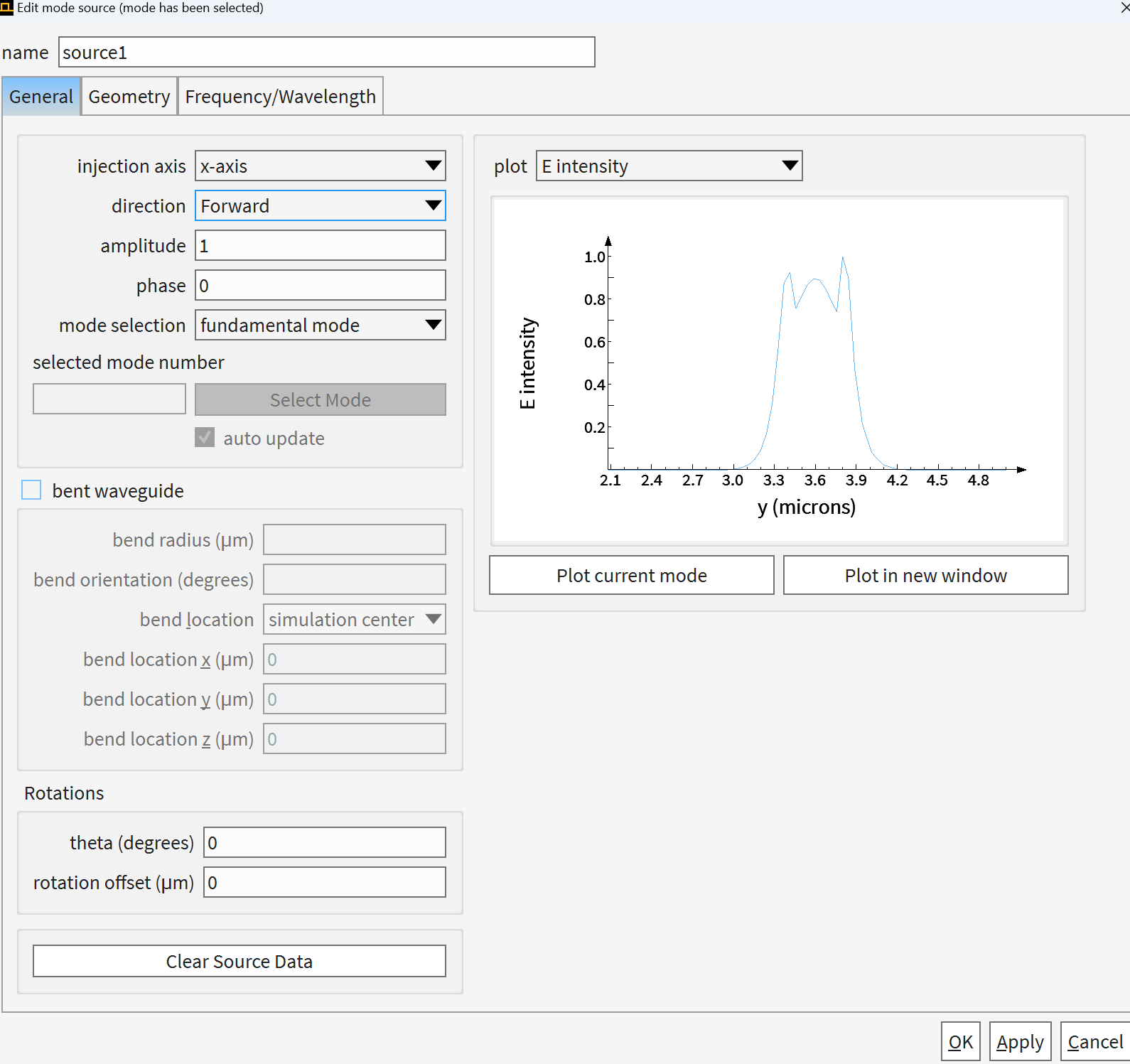
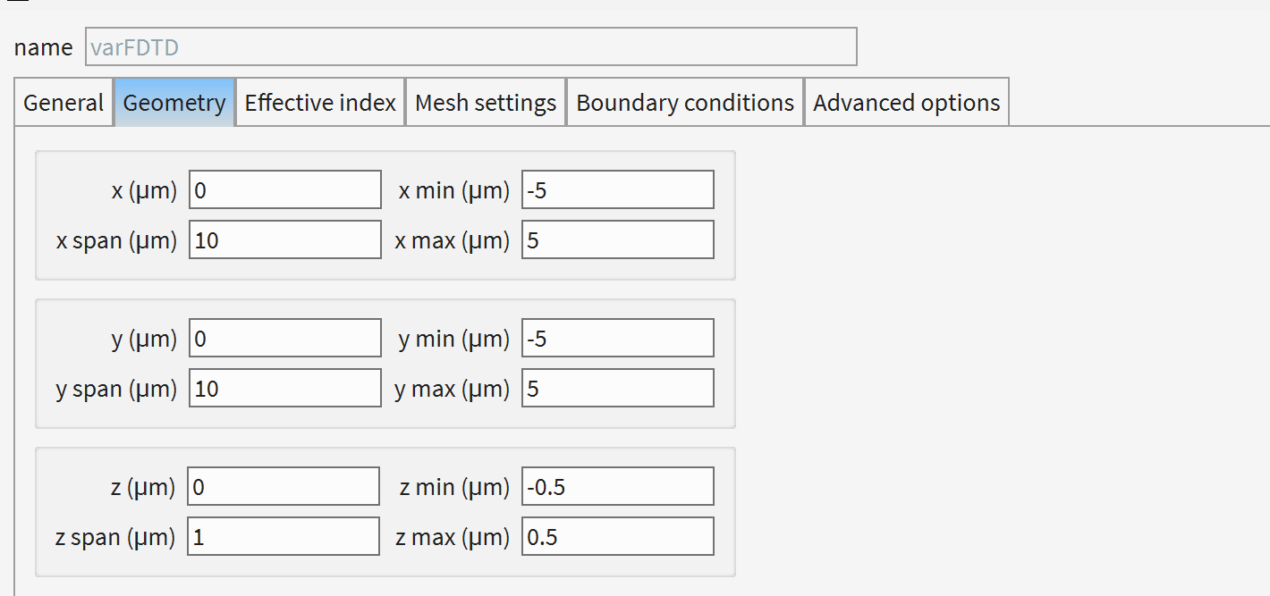
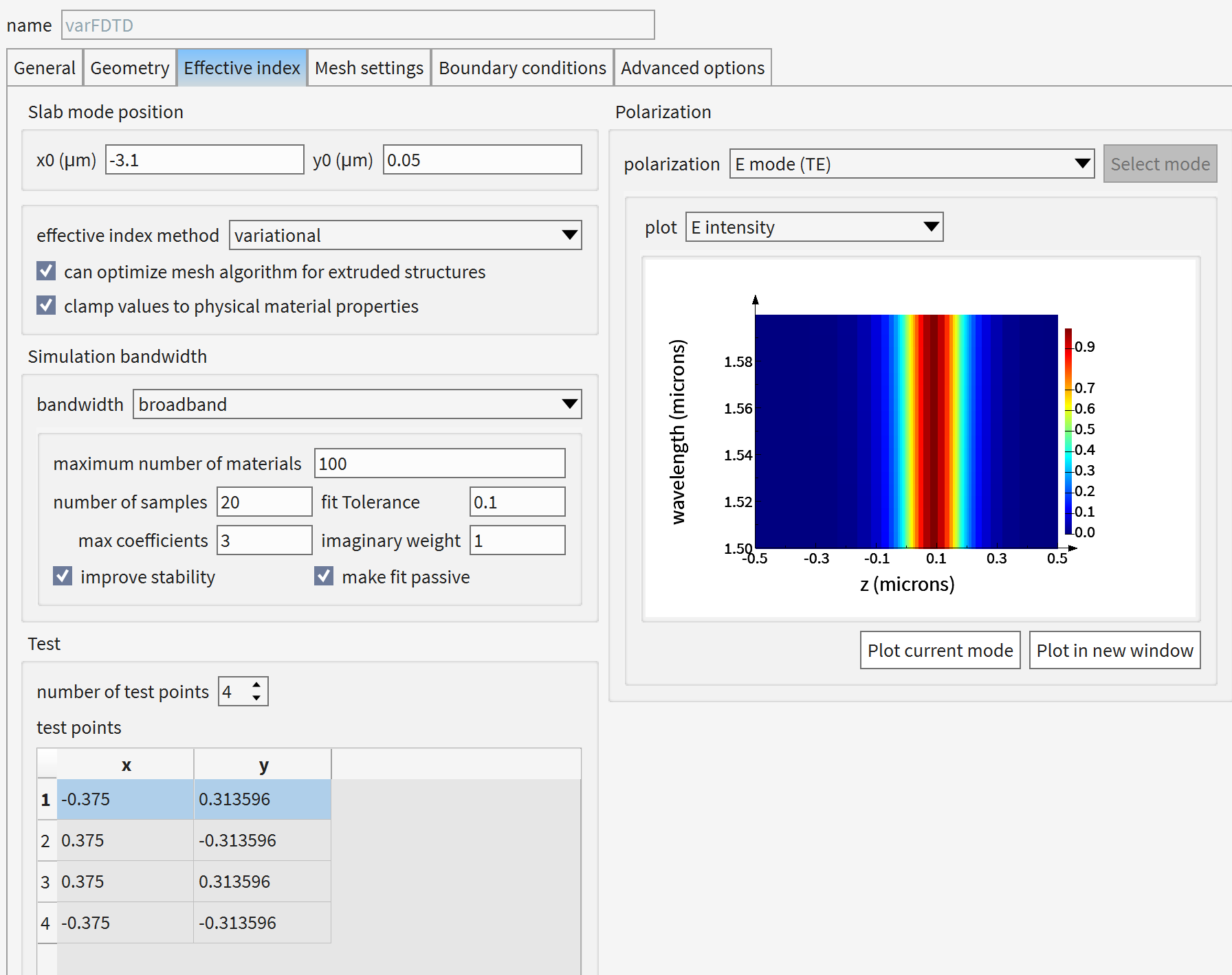
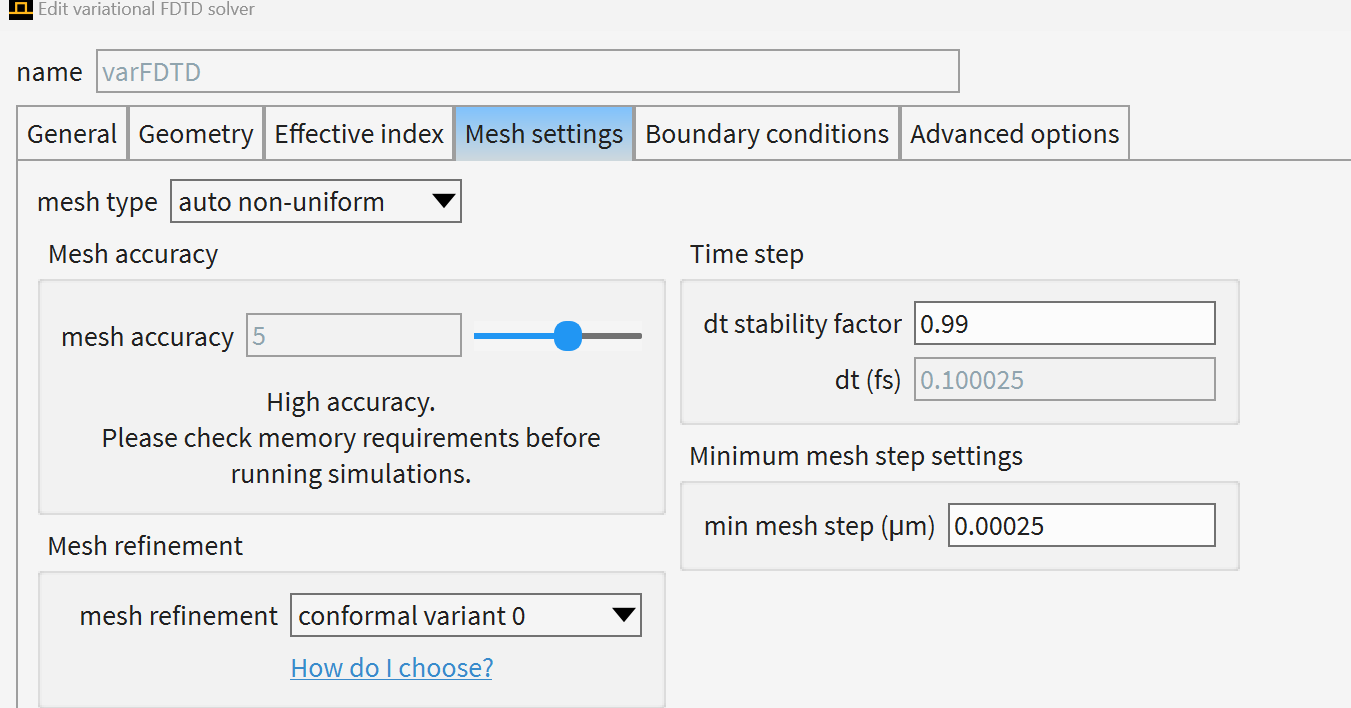
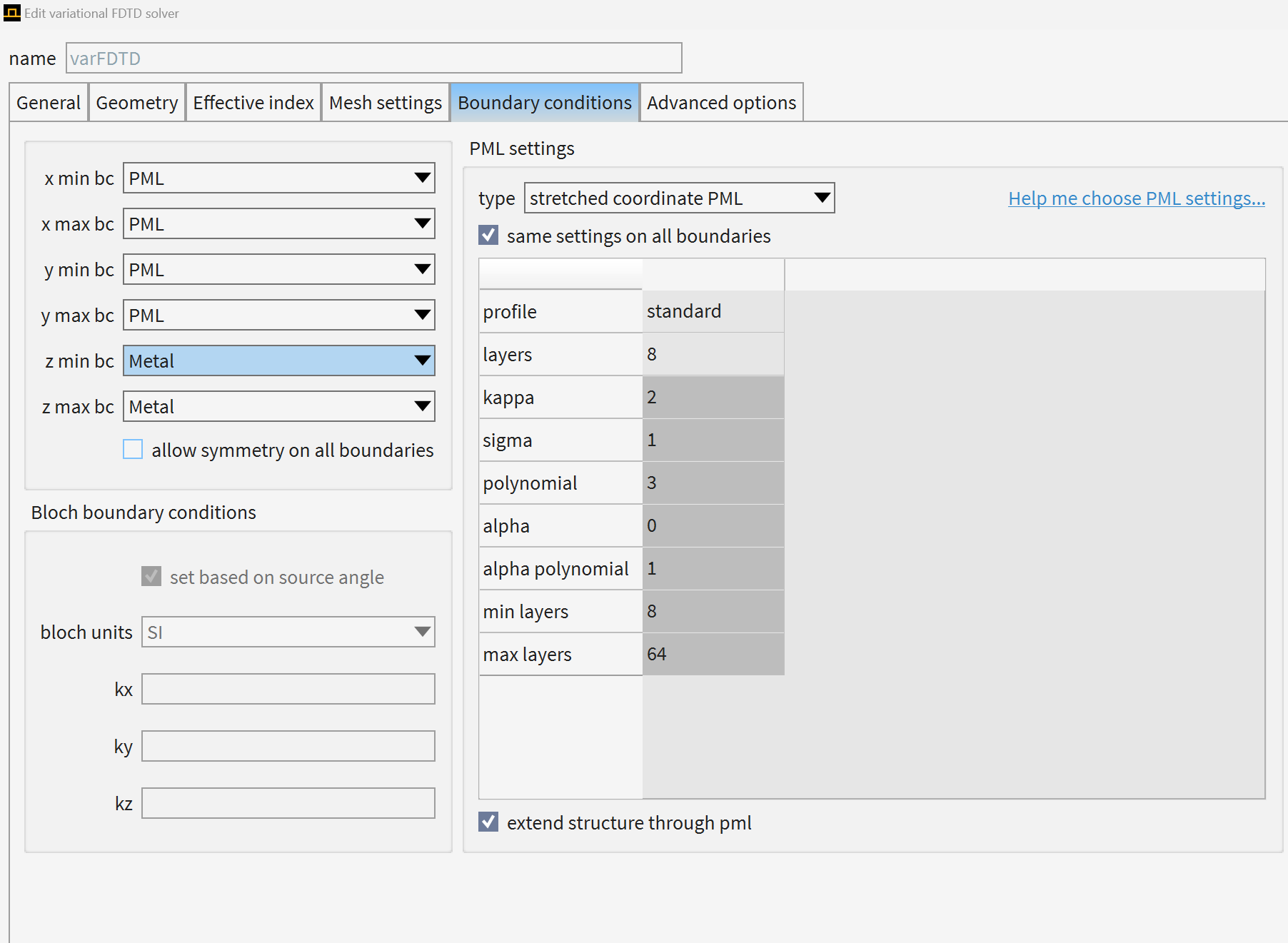
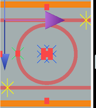
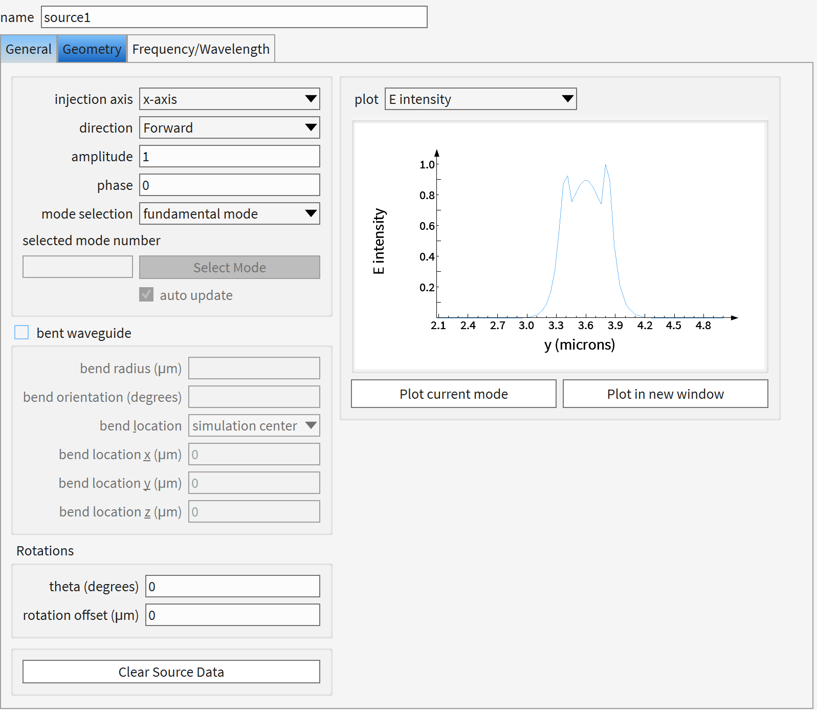
SubscriberHello. I am trying to simulate ring resonator from the following link https://optics.ansys.com/hc/en-us/articles/360042800293-Ring-resonator-getting-started-Design-and-initial-simulation . I am trying to work with varfdtd in "ring_resonator.lms" file. I have set up everything and I am just trying to see if I can get the transmission peaks at 1500-1600nm. It seems that when I set up the mode source as fundamental mode, the mode that pops up doesn't have a gaussian shape, meaning it is not a fundamental mode (screenshot attached). When I am choosing user select and click on the first mode in the list (which has the gaussian shape), then I see that it is not TE mode. The transmission I obtain is obviously incorrect (I attached the image as well). I have tried with mesh setting 5, 6, 7 and 8 (the maximum available one). Neither of these cases works. What can I do to solve this problem? I provided the screenshot of my setup as below. I didn't change anything in terms of geometry from what is originally at the "ring_resonator.lms" file on the link I provided above.

-
August 12, 2024 at 5:13 pm
Amrita Pati
Ansys Employee-
August 12, 2024 at 10:21 pm
-
-
August 13, 2024 at 9:54 pm
Amrita Pati
Ansys EmployeeHi Fakhriyya,
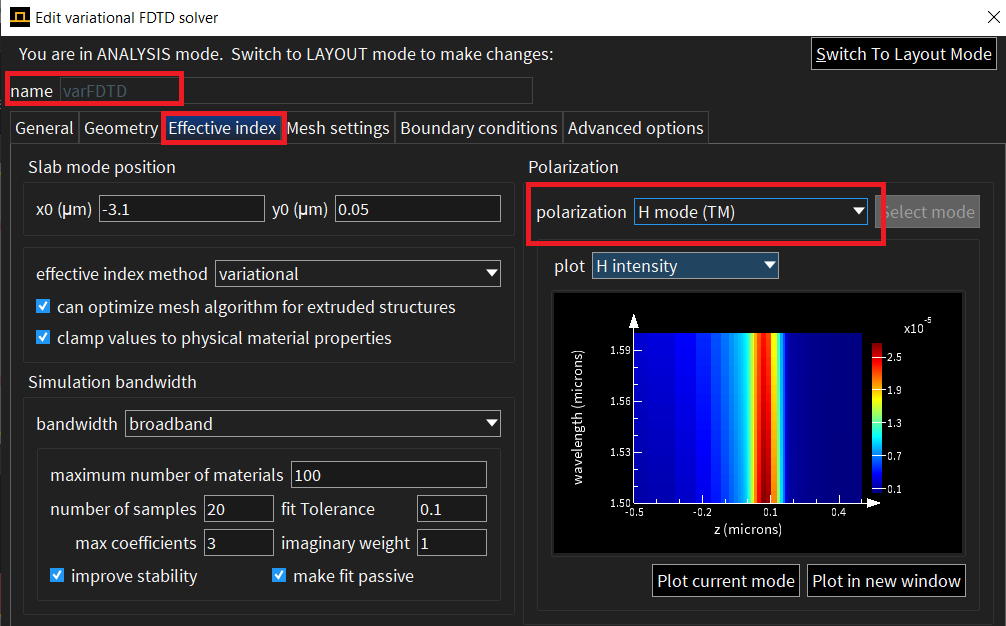
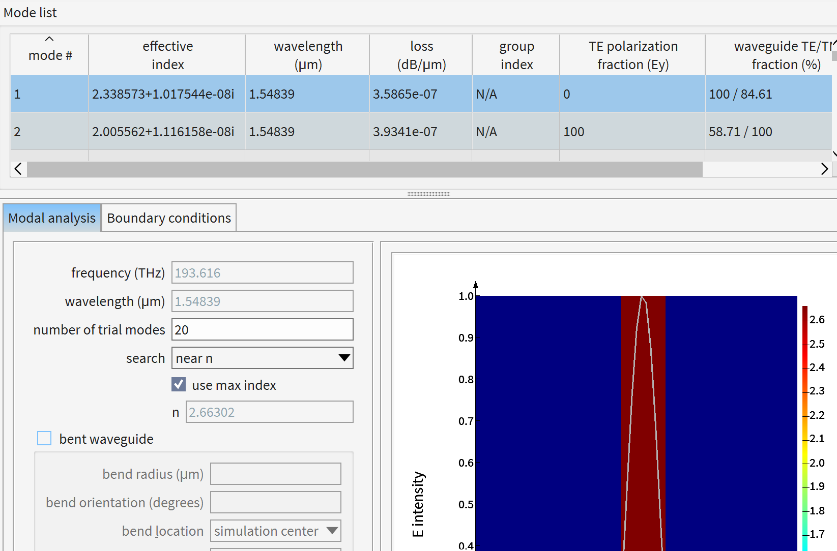
As you might know, what varFDTD does is take the vertical permittivity/index profile at a certain location, and then calculates an effective mode. And then propagates this mode in 2D to simulate the overall device. The effective mode calculation is done either under a TE framework or a TM framework. This is chosen from the Effective Index Tab of the varFDTD solver object. For example, in this case I recommended you to use the H mode (TM) because the fundamental mode is a TM mode (You can tell from the polarization fraction). In order for the varFDTD simulation to be accurate, we have to make sure that the mode we use a TE mode as a source, then the effective mode calculation should also be done under TE, and same goes on for the TM mode.
I am not sure why the device doesn't show the usual transmission dips for the TM mode, it could just be that the device was optimized for a TE mode. My understanding is that it is a very old example and it will be hard to track down who worked on this. Are you eventually planning to simulate some of your own ring modulators using varFDTD?
Regards,
Amrita-
August 14, 2024 at 12:47 pm
Fakhriyya Mammadova
SubscriberHi Amrita,
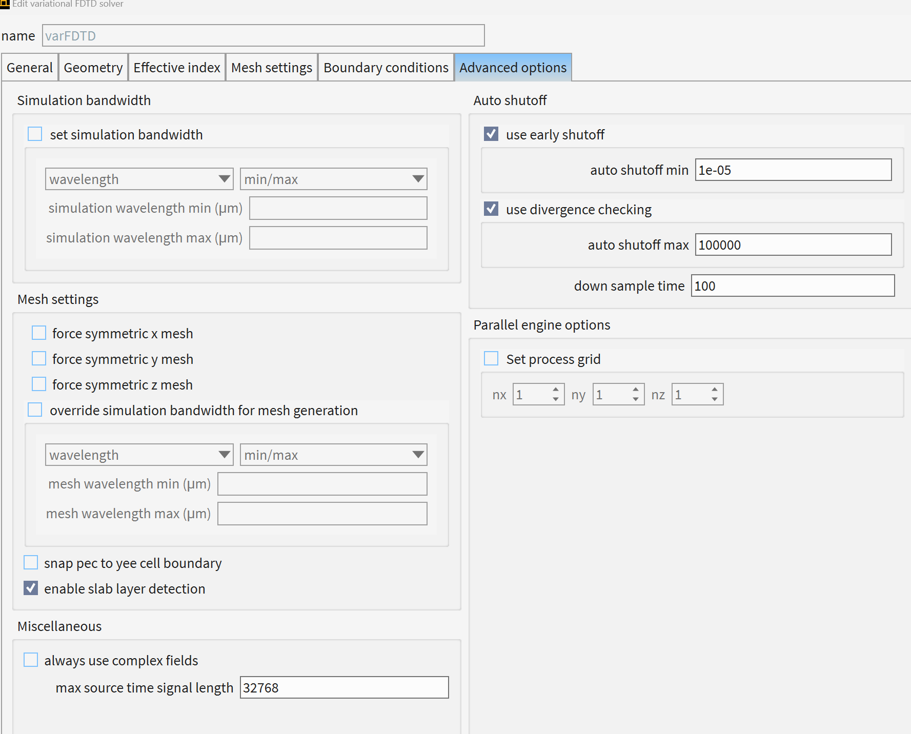
Thank you for your reply. Yes, I was trying to simulate my own examples. The mode I need is TE mode anyway, which is the one I get when I tried 3D simulations. I needed to run multiple sweeps so I decided to work in varfdtd instead because it is simply much faster. But the problem I faced was the same. It seems like no matter what I try, the fundamental mode, which the mode source can catch is TM, not TE. Which is weird, becuase the same setup in MODE FDE solver or in 3D FDTD gives TE fundamental mode.
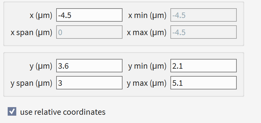
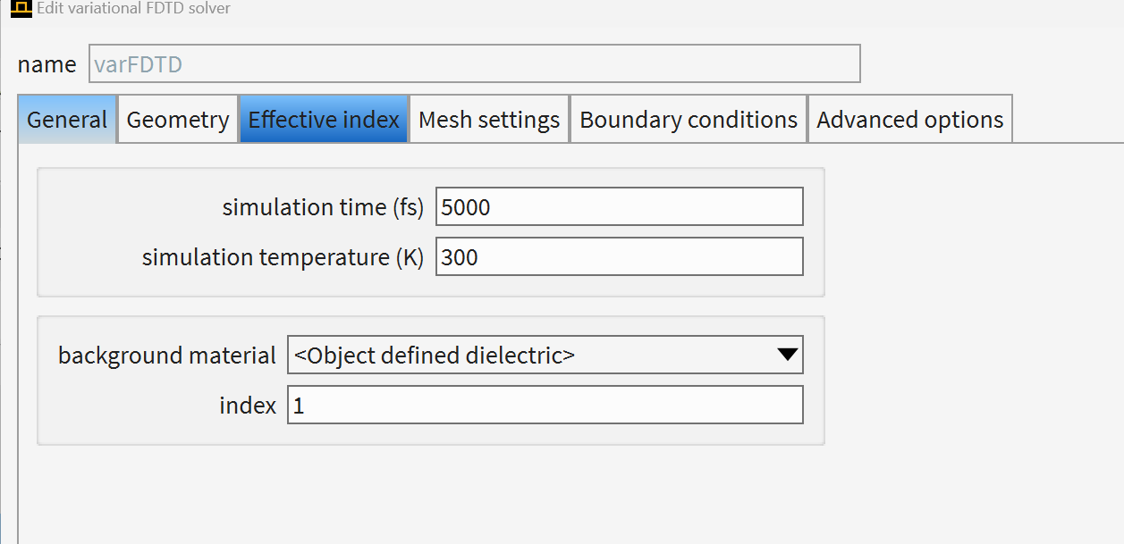
That's why I decided to try some examples from the lumerical knowledge base, because maybe I was not setting up something accurately without noticing it, so if I tried already existing examples, then everything would have been ok. So I tried the one I mentioned initially, which had the same issue. Then I even tried the one at this link https://optics.ansys.com/hc/en-us/articles/360042195693-Ring-modulator-transient-response-varFDTD . Same problem. I am not sure, maybe I am setting up the mode source or varfdtd inaccurately, so I will put the settings below.
-
-
- You must be logged in to reply to this topic.


-
3165
-
1014
-
956
-
858
-
798

© 2025 Copyright ANSYS, Inc. All rights reserved.

