TAGGED: contact, contact-behavior, rigid-body-dynamics
-
-
January 3, 2025 at 10:30 pm
oe23m012
SubscriberHello,
I am working on a thesis project involving contact modeling between a shaft and two annular ring surfaces (above and below the shaft). The analysis heavily relies on inertia forces. Below is the detailed modeling procedure and the issues I am encountering:
Modeling Procedure:
1. Ring Setup:
- The ring is connected to the ground using a revolute joint, allowing rotation in the global Y direction.
2. Slider Setup:
- A slider is connected to the ring through a slot joint, allowing translational movement in the global Z (local X) direction relative to the ring.
Â
- To limit relative rotation between the ring and the slider in the local Y direction of the slider, a frictionless contact with a restitution factor of 0.1 is defined between the slider and the ring.
3. Shaft (Rotor)-Ring Contact:
- The rotor is connected to the slider via a revolute joint.
- A forced frictional contact is defined between the rotor shaft and the ring within the small gap. This contact has a restitution factor of 0 or 0.01 and is critical because it provides the driving force for the shaft.
- The required physics here is to generate rotational torque through friction between the shaft and the annular rings. This torque arises due to gyroscopic precession, where the rotor's initial high angular momentum is affected by changes in the ring's angular momentum.
mesh
- It will work as a frictional gear
All the above image are actually a simplified model with small are to mesh and run fast but it is never able to complete the analysis
The older version with large area and with coarse mesh worked well but still not able to run the analysis till end.
Older version of the model
Mesh
Â
4. Motion Inputs:
- An initial angular velocity is applied to the rotor through the revolute joint between the slider and the rotor.
- A sinusoidal rotational motion is applied to the ring via the revolute joint.
Problem Description:
- The analysis runs successfully for lower angular velocities of rotor (e.g., 1200 RPM).
- However, when increasing the angular velocity of rotor to 4000 RPM or higher, the simulation only runs for a short duration (e.g., 0.017 s, 0.3 s, or 0.2 s) before terminating with errors.
Errors Encountered:
- State inconsistency, no relevant contact point for an active/impacting contact pair. Try reducing the time step
This is the only simmulation that ran lomg enough to see required displacement.
Efforts Taken:
- I have experimented with various mesh sizes, frictional cofficents, convex and inlined contact surfaces, different cofficent of restrituions, joints and solver settings/configurations.
- I tried with a minimum time step of 1e-15s and still didnt get it done. and in some iterations the analysis is not taking the time step above 1e-7s even if a gave 1e-15s
- Despite multiple iterations, I have been unable to achieve convergence or extend the simulation duration for higher angular velocities.
Request for Help:
I would greatly appreciate any guidance on the following points:
- How can I improve the stability of the simulation for high angular velocities (4000 RPM and above)?
- Are there specific solver settings, meshing strategies, or contact modeling techniques that could help resolve these issues?
- Could the errors be related to the restitution or frictional contact settings, and if so, what adjustments would you recommend?
- Does the joint radius and length inputs will effect the analysis?
This analysis is critical to my thesis project, and any suggestions or insights would be immensely helpful. Thank you!
-
January 13, 2025 at 7:47 am
oe23m012
SubscriberIs there any chance to simmulate the above required physics in ansys
Â
-
January 14, 2025 at 4:28 pm
dlooman
Ansys EmployeeSince you have verified the model at lower rpm values it's not obvious what you could do differently to solve for higher rpm values. A time step of 1e-15 is small enough that the contact changes are followed well. The model needs to be simplified somehow and your experience with the model is the only thing to go on. Â
-
January 14, 2025 at 6:59 pm
oe23m012
SubscriberIs there any specific reason for the termination of the solution, because if try to copy the same file and re run the analysis it is terminating the solution way earlier and I tried with multiple machines from my college server licence. almost all the times solution is terminating with this following error : state inconsistency, no relevant contact point for an active/impacting contact pair. Try reducing the time step Error found at time 8.296830e-03
-
January 20, 2025 at 3:05 pm
Jean-Daniel Beley
Ansys EmployeeHello, oe23m012. All the parts being rigid, and adding friction, you need to make sure that your model with not have redundancies, i.e. the forces in the joints and the contacts will always be uniquely defined. You can use the redundancy tool for the joints, and see if the contact is going to resolve the remaining free degrees of freedom of the model. Regarding the error that you get, and assuming that your model doesn't exibit redundancies, you have multiple ways that can improve the situation:
- Use a fine mesh on the contact
- Reduce your maximum time step
- Use the MJ time stepping algorithm
Please send the model to our technical support in case none of the above leads to a full solution.Â
-
January 22, 2025 at 9:47 am
oe23m012
Subscriberhttps://drive.google.com/file/d/1c8knD9l-4qEDQ7dBtIqVcL0vJPYZh1JH/view?usp=drive_link
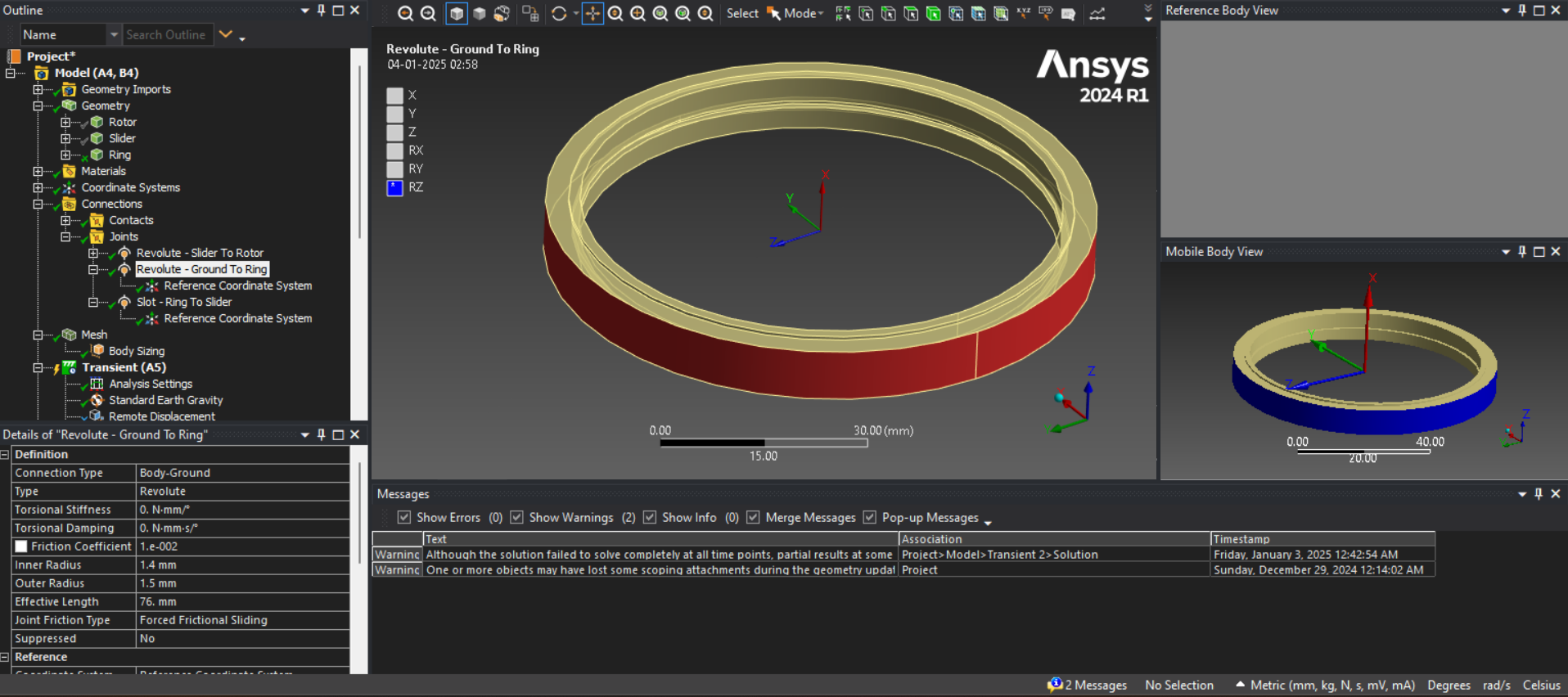
Thank you for the reply, Please find attached model for your refernce.
I have checked the redundancy analysis and it is fine, all remining 6 degerees of freedoms can be solved by the contacts.
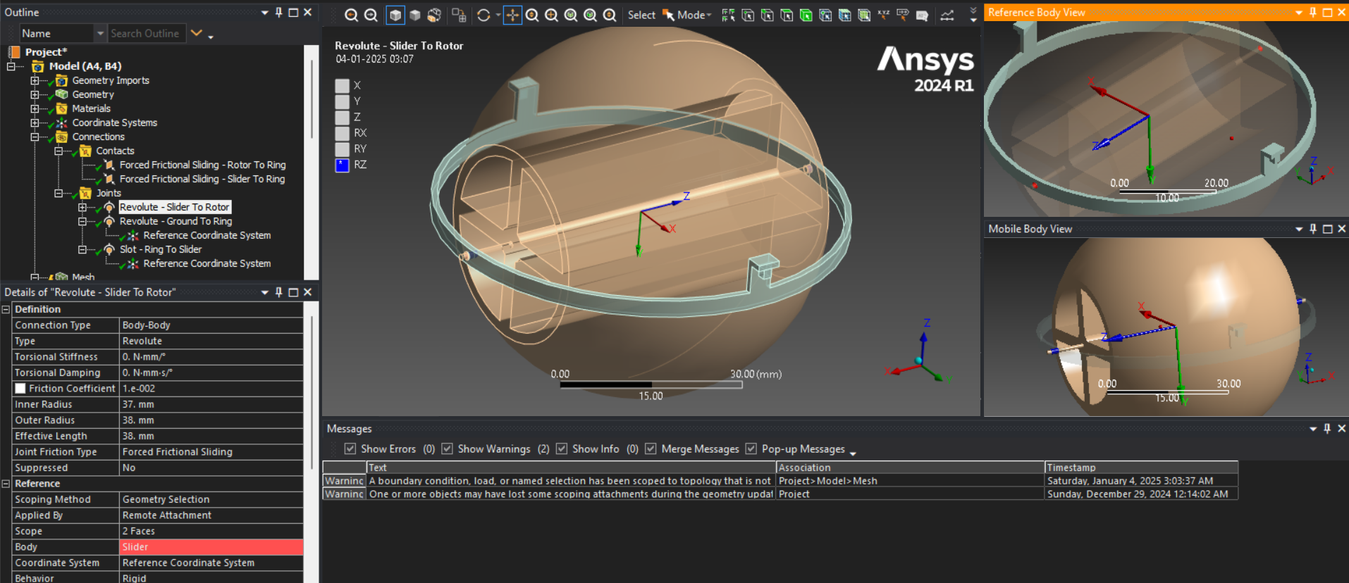
program controlled time stepping is giving accurate results even if it is terminating.
If i use The MJ Time stepping the contact position is not correct. And i need to run the analysis for atleast 10 seconds. For this computational time will be huge with a maximum time time step of 5e-5.
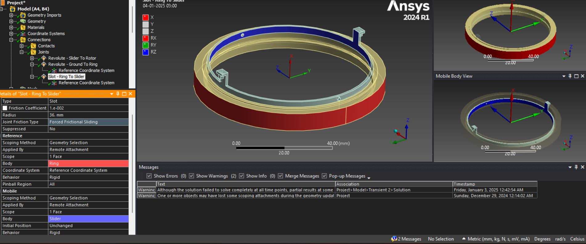
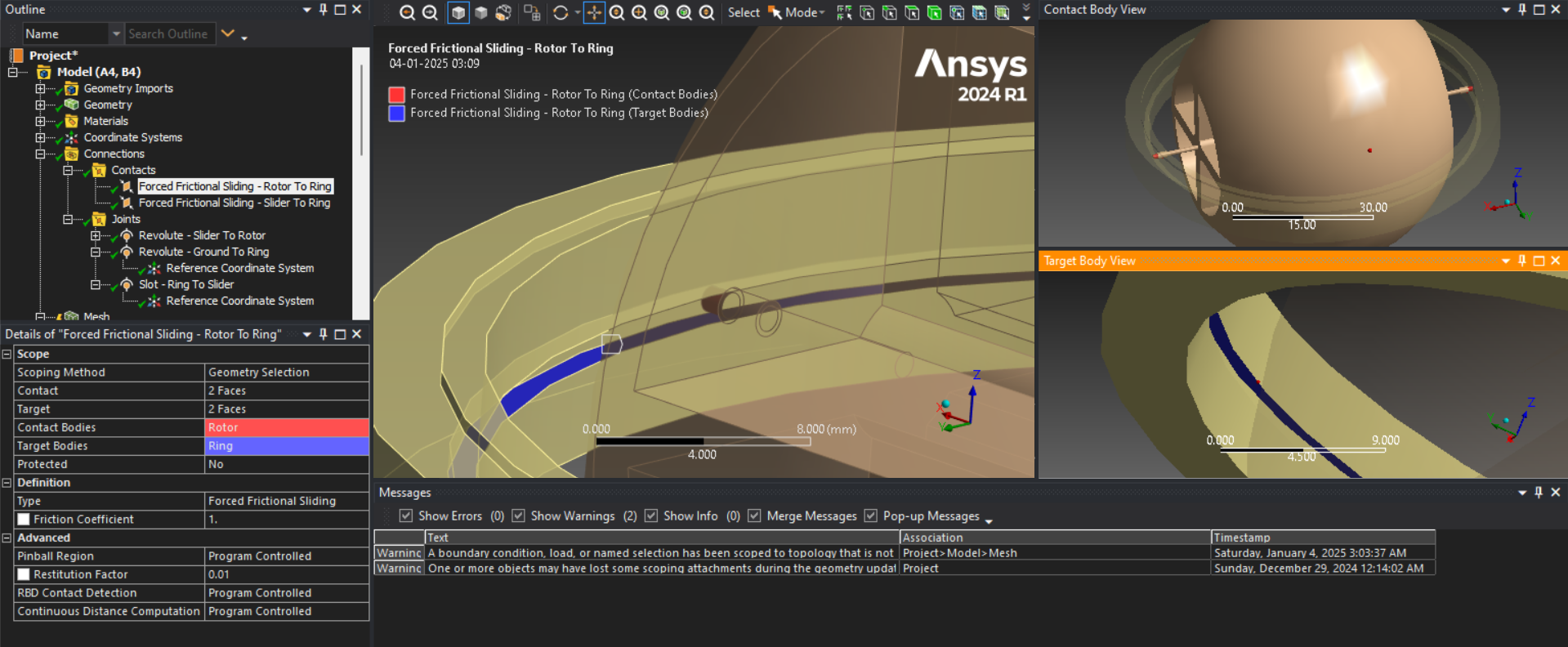
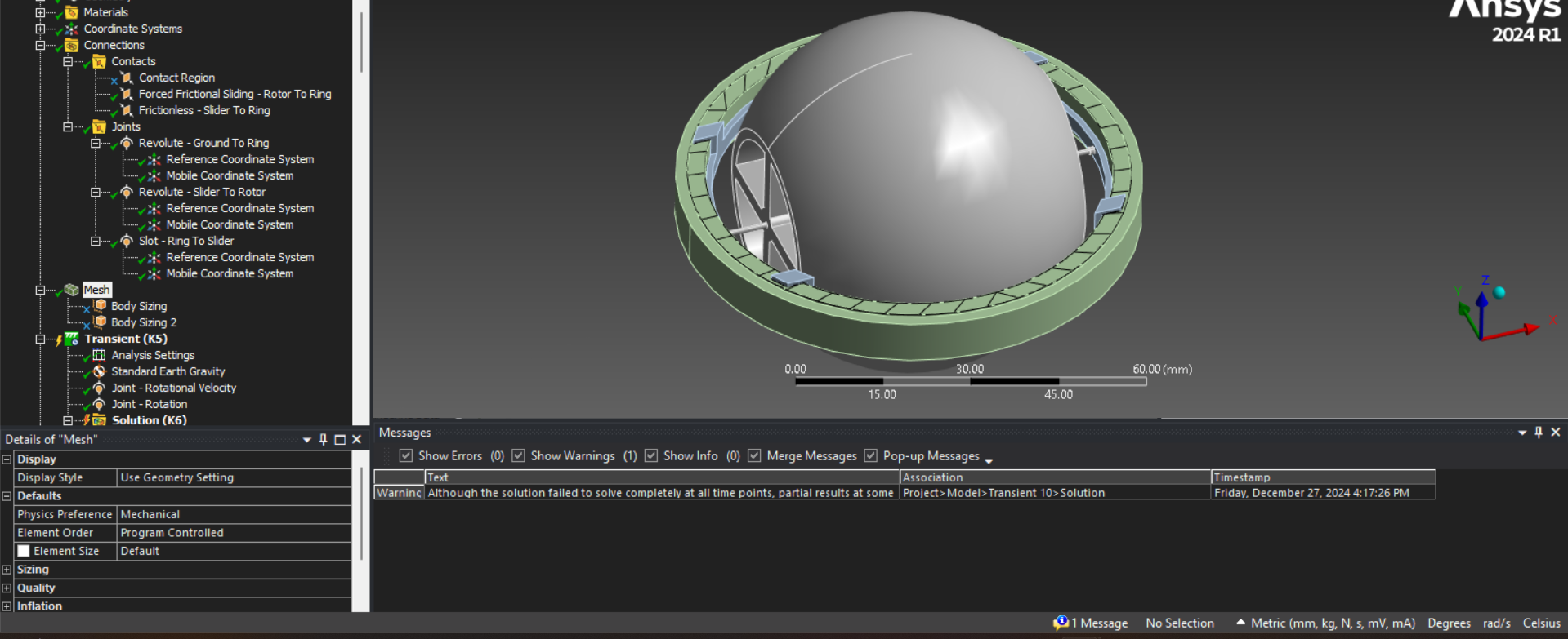
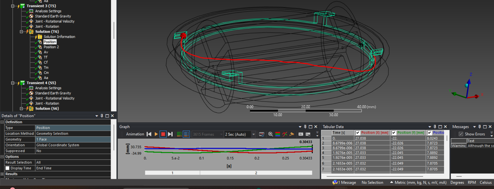
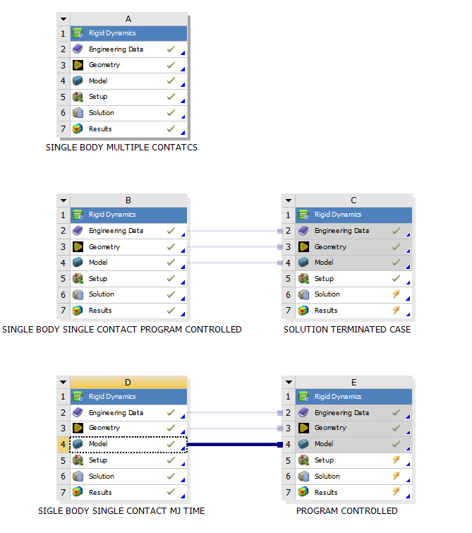
In the attached files there are three models first one is Single body multiple contatcs so its contact output is wrong.Â
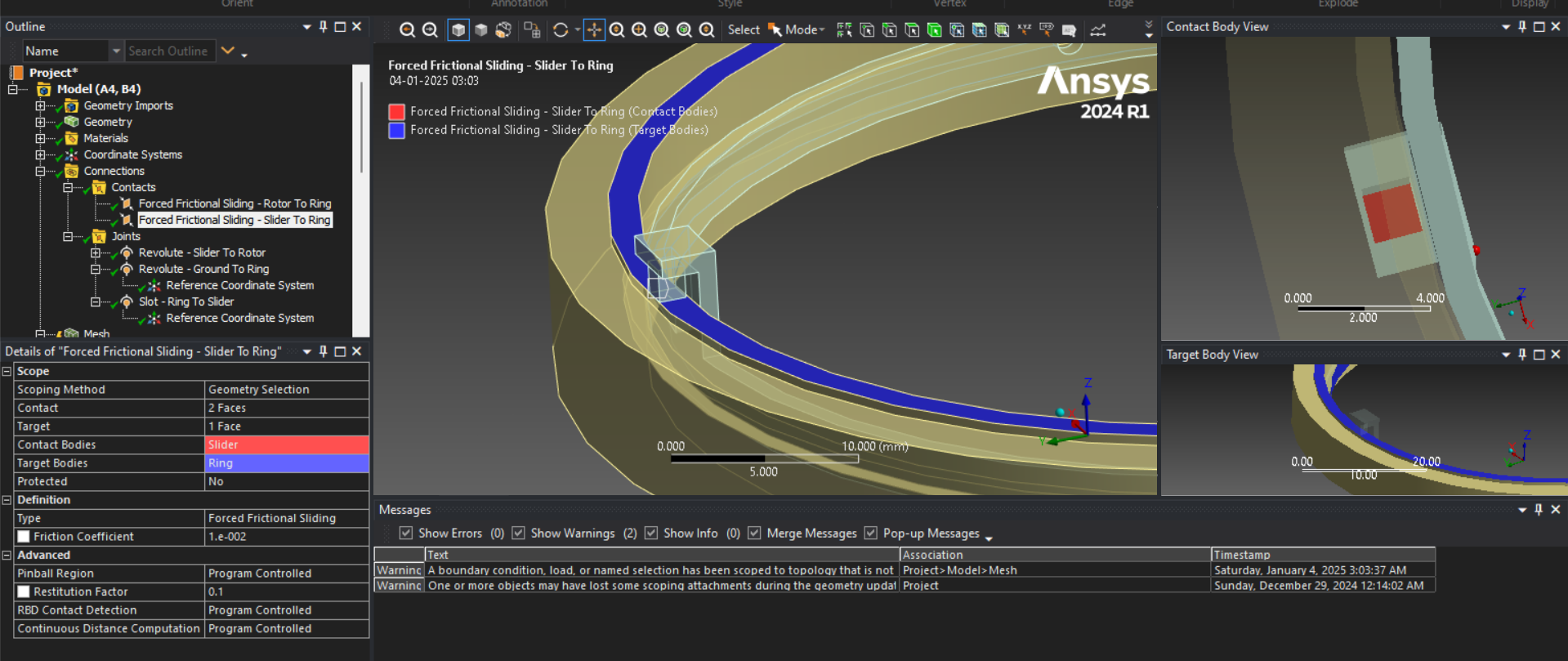
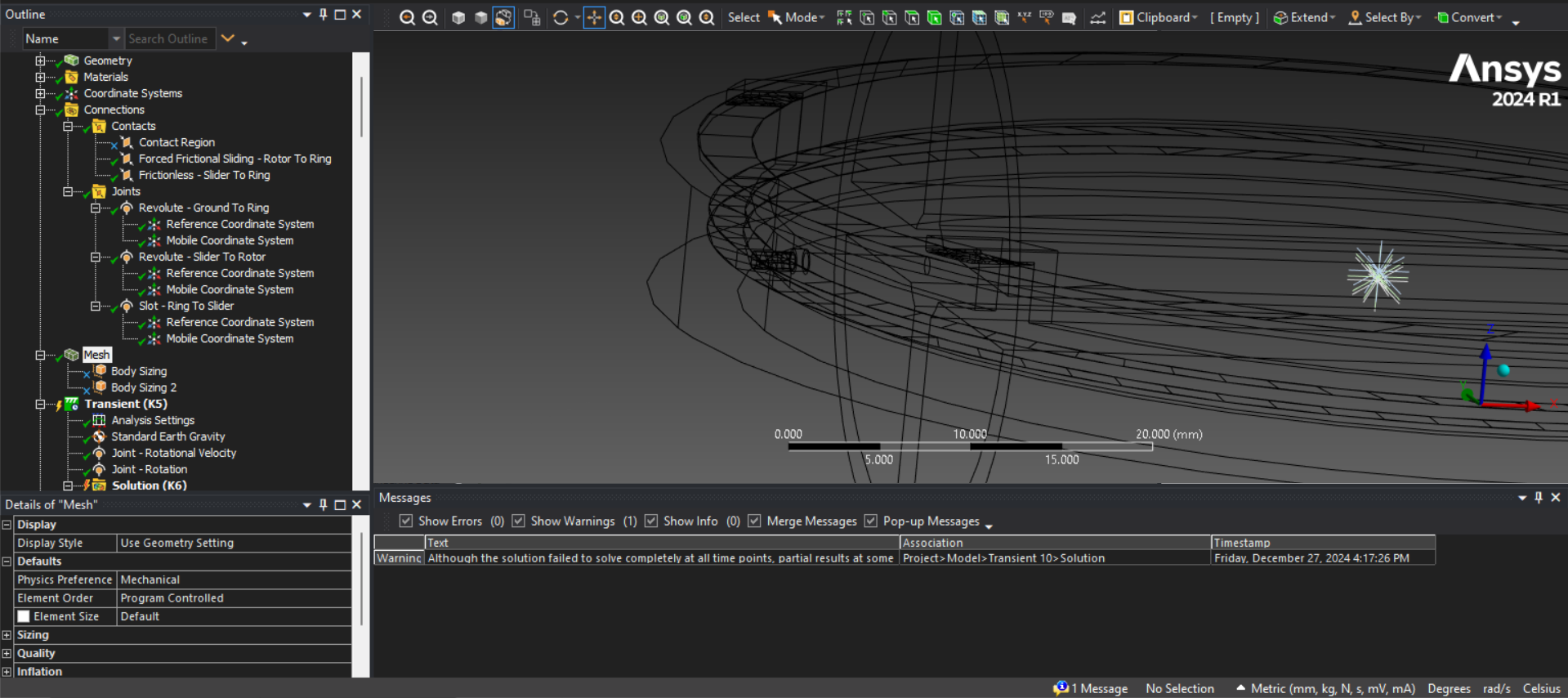
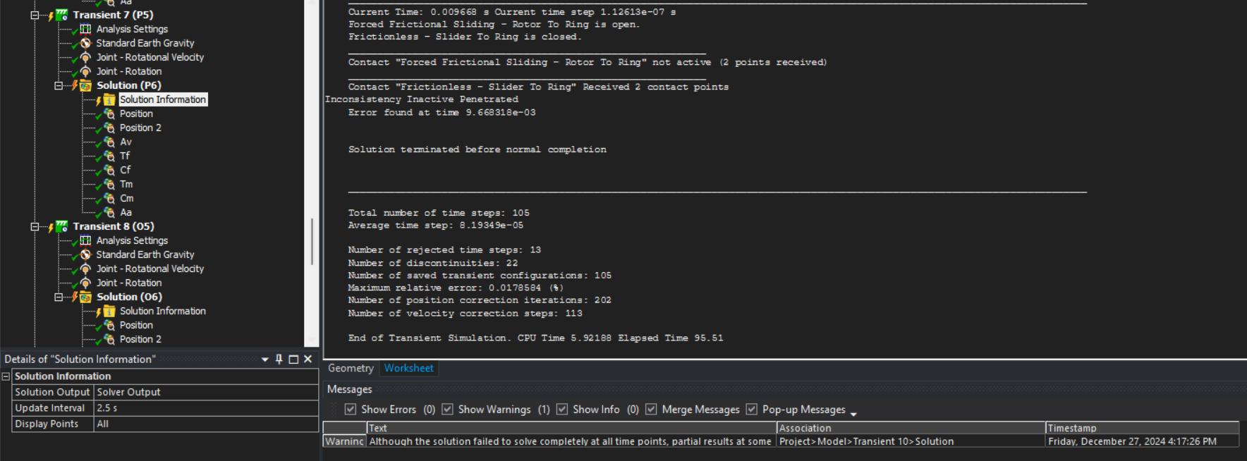
In second model i split the bodies to define contacts for different areas and it is working fine for 0.2 seconds time but after that it is terminating with errors.
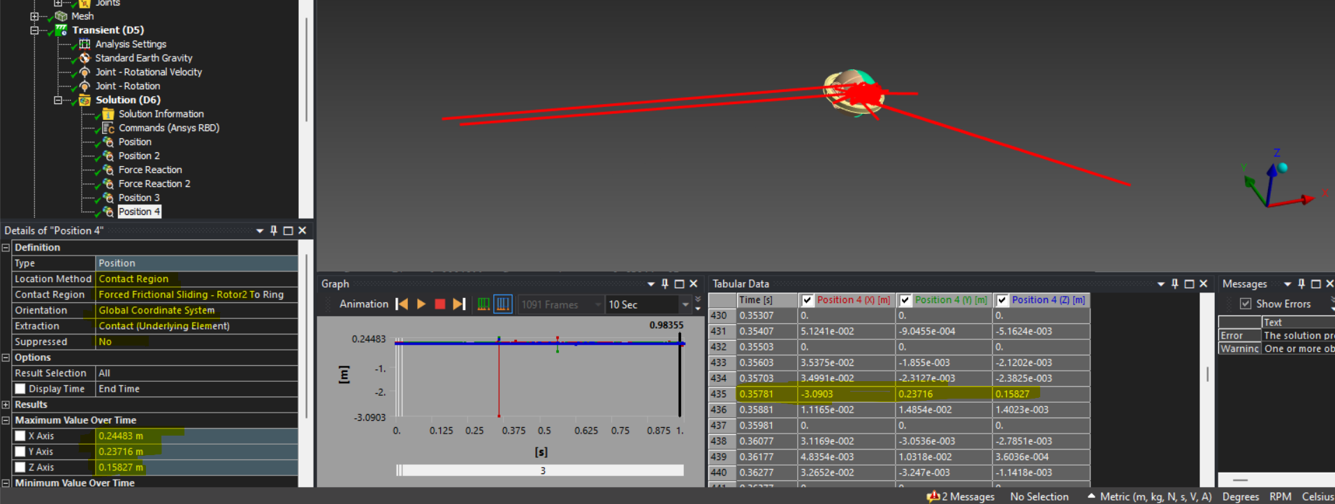
The third model is with MJ time stepping as you suggested with maximum time step but the contact results were wrong and also terminating after some time.
Thank you.Â
Â
-
January 22, 2025 at 2:26 pm
Jean-Daniel Beley
Ansys EmployeeHi oe23m012. Are you sure about your coefficient of friction? It is set to 1, which doesn't sound very realistic. It will definitely be hard to handle so much friction.Â
Regards,
JDÂ
-
January 22, 2025 at 4:48 pm
oe23m012
SubscriberÂ
Hello sir,
We can change it to 0.3. The coefficient of friction of 1 is just an ideal case for the highest friction possible. Even after changing the friction coefficient, this issue persists.
Thank you.
Â
-
January 23, 2025 at 8:35 am
Jean-Daniel Beley
Ansys EmployeeHi oe23m012. Please call your technical support, and let them know that you are in touch with me. I'll help you once we have that formally in place.Â
-
January 23, 2025 at 10:10 am
oe23m012
SubscriberÂ
Hello sir,
I have contacted the Technical team in my institution.
Thank you sir.Â
-
January 29, 2025 at 5:30 pm
Jean-Daniel Beley
Ansys EmployeeHello oe23m012. I managed to run you model with a coefficient of friction of 0.3. It takes about 20mn per second on a laptop.Â
I am using mesh-based contact detection for the contact pairs, MJ time stepping for the integration, max time step of 2.5e-4s, output control of 1000 steps, and I have a command snippet in the analysis that says "ContactUseRobustPSOR(10000)", which allow searching a bit longer for the proper equilibrium at the end of each step. Of course, when using MJ time stepping, forces need to be taken with a bit of averaging, as their value is reported at one point in time while only their integral over one time step is accurate.Â
Regards,
JDB
-
January 30, 2025 at 11:36 am
oe23m012
SubscriberHello sir,Â
Thank you so much for the help.ÂI ran the analysis withe same settings as you described and with command snippet.
as you said it ran 20 minutes for 1 secod of simulation but i tried for 10 seconds and i left the system. But after some time the ansys mechanical RBD closed automatically, i dont know for how long it ran.
And the most important thing here is the contact position output in the animation and its values. it should be in between the contacts right but it is all over the space. And reaction is also not showing in between contact and target but out of the model.
Please find the animatoin file for contact position of contac between slider and ring.
https://drive.google.com/file/d/1TG4quYrDusSTl_8qNhoiAoZNM7QVDzxD/view?usp=drivesdk
Below one is contact output between rotor shaft and slot in the ring the dia of ring its self 70mm but it is showing contact postion x at 3 meters, Please suggest me how to rectify this.Â
And out of all three models which one worked for you. I possible please share the analisis files.
Â
Best regardÂ
Kondalarao karneedi. -
January 30, 2025 at 2:20 pm
Jean-Daniel Beley
Ansys EmployeeAs said before, these forces are impact forces, that are reported at the end of the step but correspond to integrals over the previous time step. Please keep in mind that the bodies are rigid, there is no way to properly capture impact forces. If what you are after forces, either use a coefficient of restitution of zero, which might lead to bodies that stay in contact, or turn the model into a true finite element model with a mesh on the contact area that is fine enough to capture the very localized contact. I suspect that it is going to take forever.Â
Regards,
JDB
-
January 30, 2025 at 3:21 pm
oe23m012
SubscriberHi sir,
Thank you for the clarification and your help. I will try setting COR = 0 first. If that does not work, I will convert the model to a true FEM with refined mesh in the contact areas. I'll update you on the results soon.
Best regardsÂ
Kondalarao karneedi.
-
- You must be logged in to reply to this topic.
-
3467
-
1057
-
1051
-
929
-
896
© 2025 Copyright ANSYS, Inc. All rights reserved.