Ansys Products

Ansys Products

Discuss installation & licensing of our Ansys Teaching and Research products.

Response surface optimization for fluid flow

    • Adrian Ee
      Subscriber

      Hi! I am currently using the Response surface optimization software paired with the fluid flow (fluent) to determine the most ideal input parameters. To achieve so, I am required to create meshing for both the solid domain (microchannel fins) as well as fluid domain encompassing the solid domain. However, when I run the DOE, I am always met with an error. I have identified the error mainly as the contact region between the fluid and solid domain changing whenever the input parameters change (including change in angle and length of fins), which results in the stage of the process being unable to manually match the zone names of the changed contact points. Is there a way to get to automatically match the new zones names, or other ways to solve this issue.

      Thanks

    • Rob
      Forum Moderator

      There are potentially two problems here. The first is that you've not shared the topology to match the fluid-solid faces for meshing - in CAD you may have two faces in the same location but for meshing if they're not also connected the mesh won't see the "other side". For micro scale models you may also find the fin thickness is so small that automatic checks for contact (faces that aren't connected) pick up the outer faces of the fin - ie the fin is collapsed in the meshing sense. 

      Please can you post some images with the Meshing ruler visible? 

    • Adrian Ee
      Subscriber


      Not sure if this is what you were looking for. but here is part of the mesh profile. This is a screenshot taken from a top down view, and there is no changes along the Z axis. The light brown and grey shapes are the solid fins while the darker brown region with the inflation is the fluid domain. Generally all the fins used are similar to the one seen below. The Geometry was done on design modeler and the fluid domain was generated using the enclosure feature

      So far, all of the youtube videos i have seen dealing with response surface optimization requires the omission of the solid object before conducting the paramatric analysis. In the video I linked below (skip to about 21:20), the lecturer had his own reasons for omissions, but I am not sure if his paramatric analysis would still have worked had he included the solid domain portion.

      Response surface optimization reference

      Thanks for the assistance


    • Rob
      Forum Moderator

      Enclosure can be a fun one for not splitting over objects, and you then need to make sure you have a multibody part. That should resolve the contact problem(s).  In meshing you also need to fix the the way the inflation terminates around the yellow body - left hand end. Cells that shape aren't going to improve your model stability. Check inflation advanced options, there's a project or angle option in there somewhere. You also want to review the course notes on jumps in cell size, inflation mesh has it's uses, but you can also add problems into the model with them. 

      Parameters should then behave as the mesh topology and labels won't change. Caveat is that you've assembled the geometry so parameter changes don't do something daft to the shape/dimensions. 

    • Adrian Ee
      Subscriber


      I see, thank you! Will look through the course notes and see how i can incoporate it to my final geometry.

      This isnt actually meant to be as detailed, as i intend to use the data from the response surface optimization process to narrow down to few dimensions before coming up with a more detailed gemoetry and meshing. However the main issue that i face is that the fluent process is unable to auto update the change in contact regions between the fluid and solid domain whenever theres a change in dimensions of the fins, not so much that of the mesh process. Not sure if that can be solved.

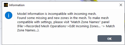
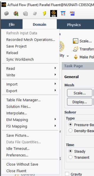
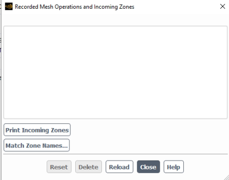
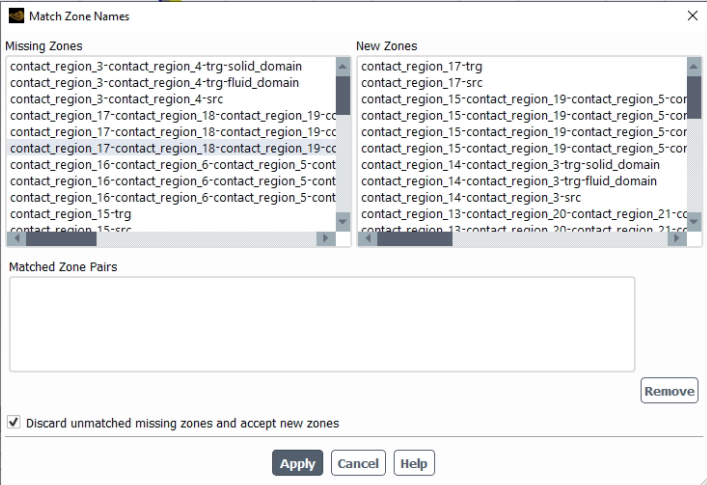
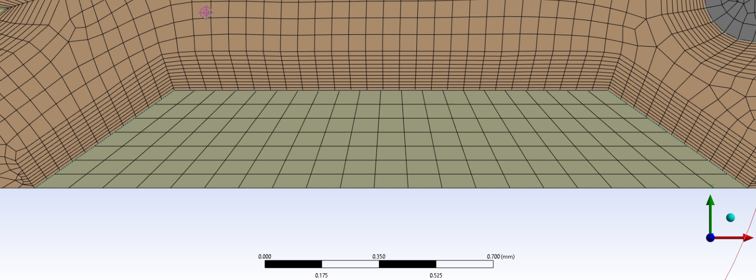
      edit: this is an example of the error i get when i change the width of the fin, the error i receive is a result of the contact points between the solid fin and fluid domain shifting and ansys fluent is unable to register it. It requires me to manually go to , and to update the changes in contact regions, before i am able to proceed with the calculations 


    • Rob
      Forum Moderator

      There may be a slight difference in labels in the interface zones, and that can break the parameter updates. A conformal mesh should reduce the chances of problems. 

    • Adrian Ee
      Subscriber

      Ive updated the post for better understanding of the problem faced.

      Will try creating a conformal mesh, although not sure if that works since there is still a change in contact regions, will update here again. Thanks!

    • Rob
      Forum Moderator

      Fluent will complain the first time once the interface zones are removed and then should work as intended. The root issue is the boundary ID may not be retained for every change, and that confuses the workflow. 

    • Adrian Ee
      Subscriber

      In a way, the only ideal situation is to find a work around by conducting the response surface optimization simulation on only the fluid domain? (i.e. not hving the solid domain present in the simulations not having a contact region to consider)

    • Rob
      Forum Moderator

      Once you share topology (multibody part in DM) the problem should go away. You then have an interior surface between the zones and provided you label everything correctly updates will work.  

    • Adrian Ee
      Subscriber

      I was able to get it to work, thank you for the assistance!

Viewing 10 reply threads
  • The topic ‘Response surface optimization for fluid flow’ is closed to new replies.