
-
-
August 4, 2020 at 5:35 pm
nlj007
SubscriberHello. I would like to displace a body relative to another body in ANSYS Transient Structural. Here is a 1D example of what I would like to do. There are 4 blocks connected by springs and confined to 1D motion in the X axis. The far left block is fixed. I would like to increase distance A by 0.1m and observe the response of point P.
In reality, the gap between A represents a linear motor that will push these two bodies apart to a set position. I am interested in the true response of point P. If the motor separates by 0.1m, point P will actually overshoot this setpoint by some amount and settle to the setpoint given that it is appropriately damped.
August 4, 2020 at 8:58 pmSubscriberI'm not sure what happened with the formatting here. I am attaching the referenced image in this commentn n
August 4, 2020 at 10:17 pm
n
August 4, 2020 at 10:17 pmSai Deogekar
Ansys EmployeeHi,nI am not sure I understand why you chose to model the linear motor as a spring. May be you can use Constraint equations to define the relative displacement between blocks 2 and 3? But the constraint equations along with a spring between them will lead to over-constrain.nHere is how you can define Constraint equations:nnHope this helps,nSainAugust 5, 2020 at 2:06 ampeteroznewman
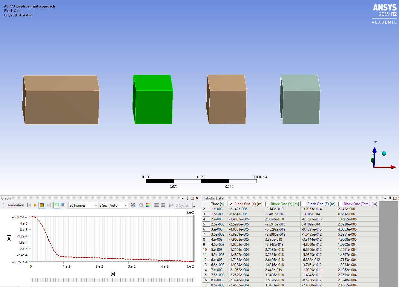
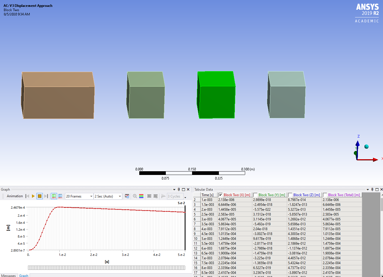
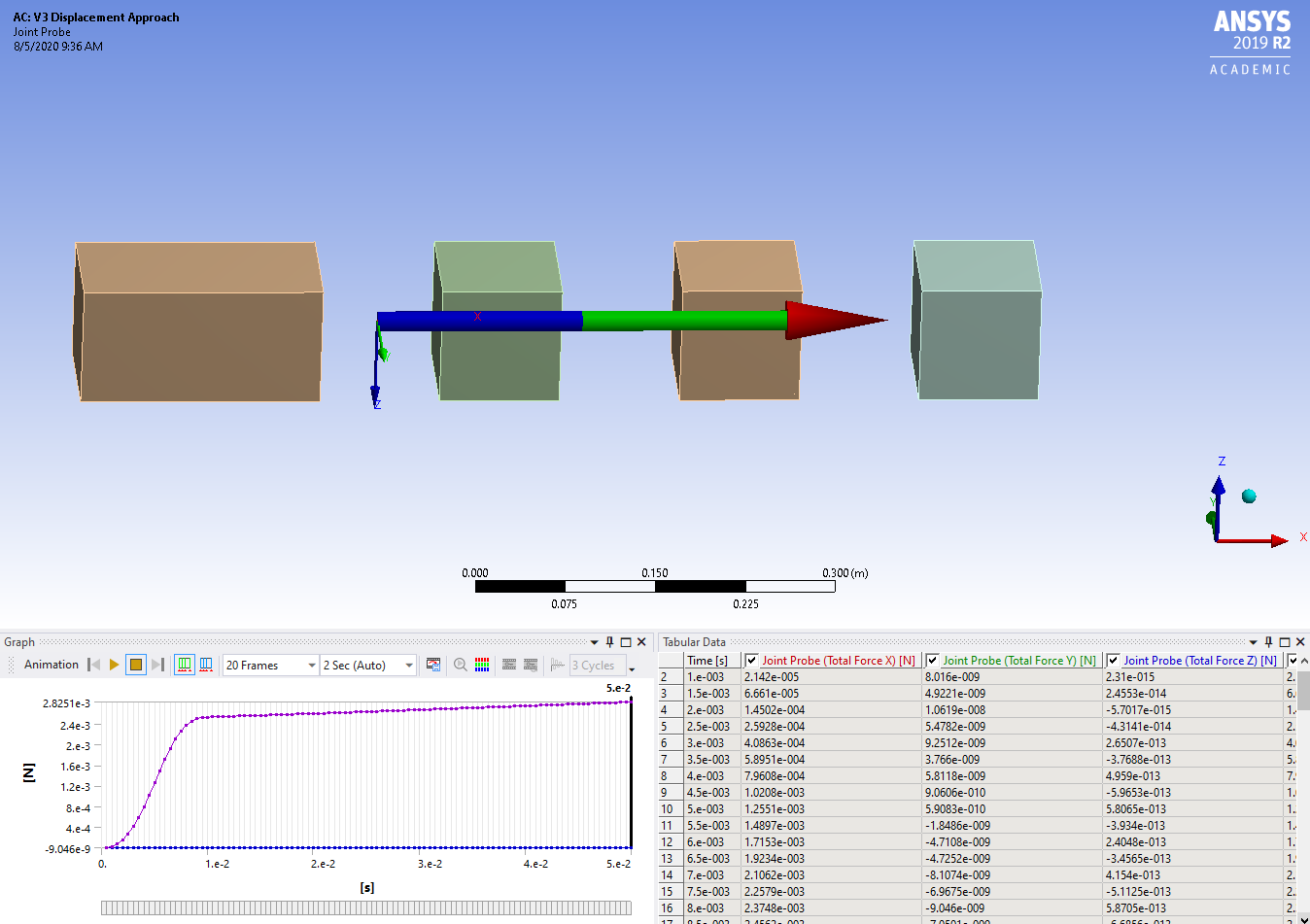
SubscriberLabel the first body on the left Ground and the bodies that move as: One, Two and Three so that the gap between One and Two is measured as A and the point P is on body Three. nI suggest you put a translational joint between One and Two and add a Joint Load. The joint load can be a Displacement function of time that ramps the displacement of 0.1 m over some time interval. A linear ramp is the simplest way to change the distance between the bodies. An S-shaped displacement-time curve would be a more natural way to increase the displacement.nAugust 5, 2020 at 2:14 pmSubscriberThank you both for the responses.nSai,nThe spring was an error in the diagram I posted. In reality, there would not be a spring between blocks One and Two following peteroznewman's naming convention. I just tried out the constraint equation, and I think the problem I have with it is that the constraint equation does not induce any motion. It only relates the motion of one body to another. I have a specific motion profile I would like apply to this displacement. However, maybe I am missing something that would make the constraint equation work in this case and allow me to induce motion using it.nnote: I am using general joints instead of springs in the screenshots belownPeteroznewman,nI actually ran across the joint displacement yesterday afternoon and spent some time messing around with it. The issue I have is that the displacement of the joint itself seems to be locked in position and not allowed to displace such that the system reaches an equilibrium. If I ramp the joint displacement to 5e-4 m, each block displaces 2.5e-4 m and is held in that position through the rest of the time steps. I have attached screenshots and my files showing this. The behavior where each block displaces away from the center of the joint is okay, but I would like for the system to then settle to an equilibrium, which, in this case, would mean the far left spring returns to its original length instead of staying compressed as you see in the screenshots.nI have tried the Lock at Load Step option, and I have tried to deactivate the joint displacement at the time steps after 5e-4 m is reached with no luck. I have also looked in to the difference between remote vs. direct attachment for the joint connections, but changing that didn't seem to help either. However, there may still be something there that I'm missing.nnI have been working on this for a week or two, and I feel that this is the closest I have come to an effective and straightforward solution, so any advice would be greatly appreciated!n
 Archive project file:https://drive.google.com/file/d/19wDSIxmRtygCk6bLCzAH3epzXzu2AtnH/view?usp=sharingn
August 6, 2020 at 1:56 amSubscriberAttached is your blocks and joints but I added springs of 1000 lbf/in between each block. I added a Modal system to learn that the modal frequencies of this system are about 30 Hz, 83 Hz and 120 Hz. Knowing those frequencies helped me choose the End Time and Time Increments for the Transient solution. I also added some damping in the Damping Controls.nHere is a plot of point P. I think this is the type of plot you were looking for.n
Archive project file:https://drive.google.com/file/d/19wDSIxmRtygCk6bLCzAH3epzXzu2AtnH/view?usp=sharingn
August 6, 2020 at 1:56 amSubscriberAttached is your blocks and joints but I added springs of 1000 lbf/in between each block. I added a Modal system to learn that the modal frequencies of this system are about 30 Hz, 83 Hz and 120 Hz. Knowing those frequencies helped me choose the End Time and Time Increments for the Transient solution. I also added some damping in the Damping Controls.nHere is a plot of point P. I think this is the type of plot you were looking for.n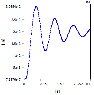 August 6, 2020 at 3:04 pmSubscriberUnfortunately I have 2019 R2, so I can't open that archive. However, I notice on the graph you posted that the displacement of P appears to be settling somewhere around 2e-2m. Since the joint displacement is 5e-2, point P should settle to 5e-2. I think this is due to the joint not being able to displace freely for some reason. Instead, the blocks are pushed apart by ~0.5x the displacement.nHowever, I found a solution that worked quite well for me. I added a bar between blocks 1 and 2 with an orthotropic secant coeficient of thermal expansion in the X direction equal to 1/L where L is the original length of the beam. I also gave this part a very high stiffness relative to the other parts. I then set the reference temperature by body for this part to 0 C. This means that each degree of temperature change equals 1m of expansion (delL/L = alpha*delT --> delL = alpha*L*delT, alpha = 1/L --> delL = delT).nWith this method, I can assign a tabular temperature change to this part. Here is a gif of the response and below is a plot of the response. As you can see, point P (TCP) settles to the correct commanded value.n
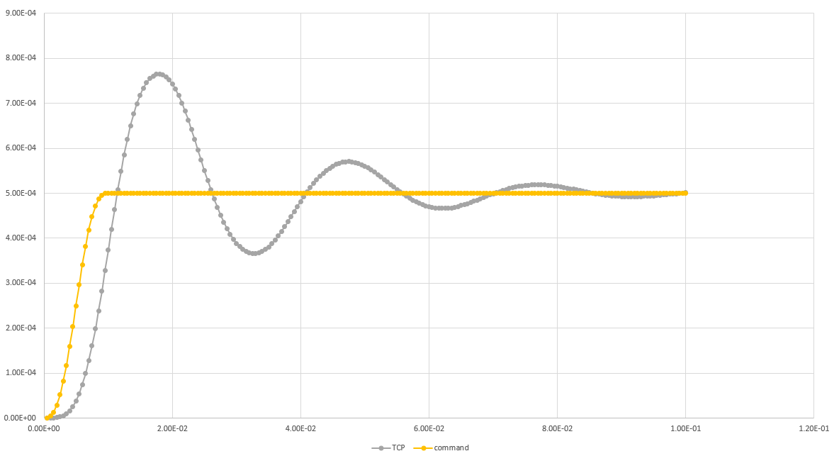 n
August 6, 2020 at 5:38 pmSubscriberlnj007, nI used the table of joint displacement that was in your model. It smoothly went up to nearly 0.02 m which matches where the point P was trending toward.n
n
August 6, 2020 at 5:38 pmSubscriberlnj007, nI used the table of joint displacement that was in your model. It smoothly went up to nearly 0.02 m which matches where the point P was trending toward.n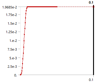 n
August 7, 2020 at 12:51 pmSubscriberI agree that the model attached trends toward 0.02m, but with a displacement of 0.05, the final displacement of P should settle at 0.05m. If you look at the original diagram and think about A expanding by 0.05, it is clear that point P would eventually settle 0.05m to the right of its original location. I believe that the fact the joint displacement does not give this result means that something is not working as I expected. I detailed another approach in a previous response that worked for me, but I am certainly open to the joint displacement method as it seems like a more direct solution. However, I would need to understand and change whatever is causing the joint itself to stay fixed in position.nAugust 8, 2020 at 11:09 pmSubscriberThe displacement applied to the joint is approx. 0.02 m. That is the graph shown in my post. That curve came from your model. Nowhere in that model is a displacement of 0.05 m used. There is nothing to understand about why it doesn't reach 0.05 m because the input was 0.02 m.nThe joint displacement load specifies the distance increase between blocks One and Two. It is not fixed to ground. Both blocks are free to find equilibrium. If you applied a gravity load along the X axis, then the equilibrium position of block One would not be were it was initially, but would be some distance along the X axis.nViewing 9 reply threads
n
August 7, 2020 at 12:51 pmSubscriberI agree that the model attached trends toward 0.02m, but with a displacement of 0.05, the final displacement of P should settle at 0.05m. If you look at the original diagram and think about A expanding by 0.05, it is clear that point P would eventually settle 0.05m to the right of its original location. I believe that the fact the joint displacement does not give this result means that something is not working as I expected. I detailed another approach in a previous response that worked for me, but I am certainly open to the joint displacement method as it seems like a more direct solution. However, I would need to understand and change whatever is causing the joint itself to stay fixed in position.nAugust 8, 2020 at 11:09 pmSubscriberThe displacement applied to the joint is approx. 0.02 m. That is the graph shown in my post. That curve came from your model. Nowhere in that model is a displacement of 0.05 m used. There is nothing to understand about why it doesn't reach 0.05 m because the input was 0.02 m.nThe joint displacement load specifies the distance increase between blocks One and Two. It is not fixed to ground. Both blocks are free to find equilibrium. If you applied a gravity load along the X axis, then the equilibrium position of block One would not be were it was initially, but would be some distance along the X axis.nViewing 9 reply threads- The topic ‘Relative Displacement in Transient Structural’ is closed to new replies.
Innovation Space Trending discussions
 Top Contributors
-
peteroznewman
 6379
6379 -
scabo
 1906
1906 -
Dennis Chen
 1457
1457 -
javat33489
 1308
1308 -
Shyam Prasad V Atri
1022
Top Rated Tags
© 2026 Copyright ANSYS, Inc. All rights reserved.
Ansys does not support the usage of unauthorized Ansys software. Please visit www.ansys.com to obtain an official distribution.
-


The Ansys Learning Forum is a public forum. You are prohibited from providing (i) information that is confidential to You, your employer, or any third party, (ii) Personal Data or individually identifiable health information, (iii) any information that is U.S. Government Classified, Controlled Unclassified Information, International Traffic in Arms Regulators (ITAR) or Export Administration Regulators (EAR) controlled or otherwise have been determined by the United States Government or by a foreign government to require protection against unauthorized disclosure for reasons of national security, or (iv) topics or information restricted by the People's Republic of China data protection and privacy laws.
