-
-
September 2, 2024 at 8:40 am
muhammadaziz.sarwar
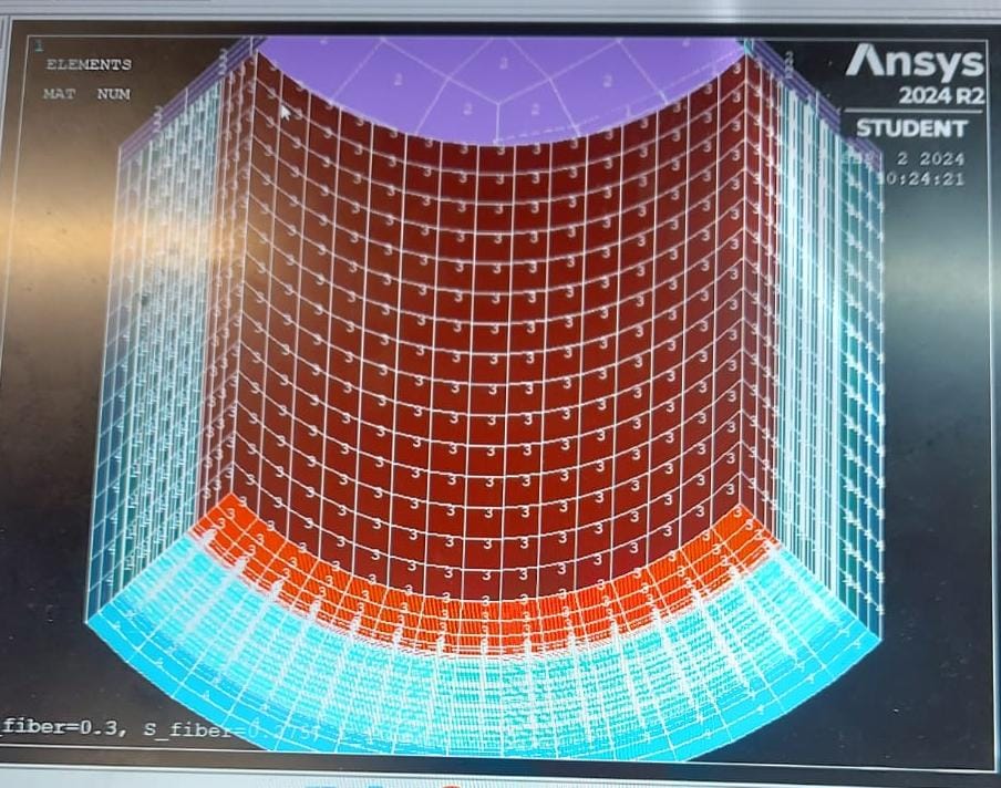
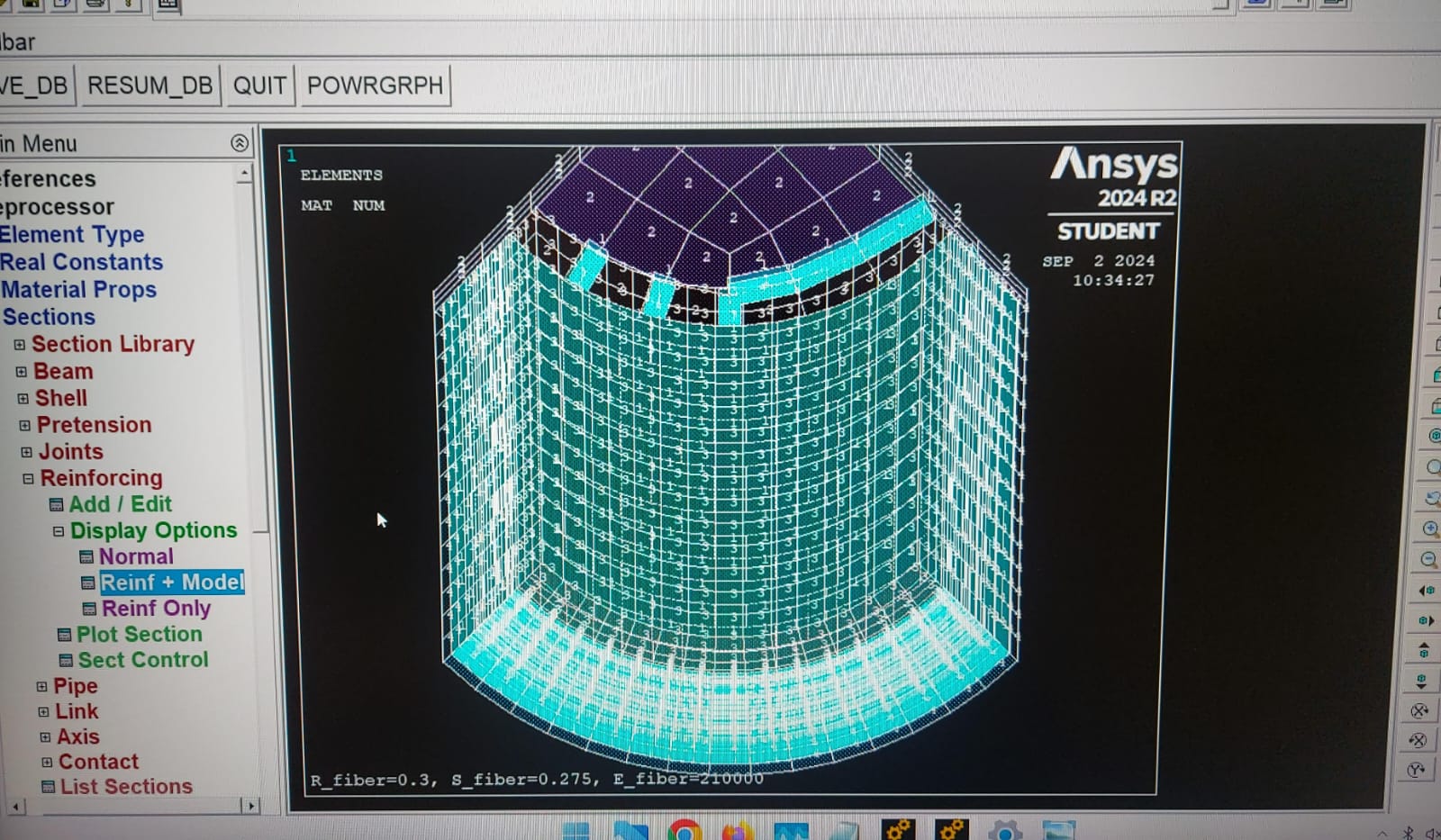
SubscriberHi everyone I am using Reinf265 with solid 185 as steel wire reinfocements for spiral arrangements of wire along tube.Its a hydraulic tube consists of rubber as base material and 4 layers of steel wire as reinforcements.My model consists of three types of rubber material and steel wire reinforcements.Please comment is smeared reinforcing approach is okay to use,or discret approach should be used I have a problem material 2 in my model represnts as steel and material 1 represents base rubber material.In reinforcing section material 2 is alloted to reinforcement with other properties like area,spacing etc but when i tried to check the material of reinforcing it is still showing base material 1,is it normal or it should represents material2.please check my model.I am thinking reinforcement is not applied correctly. First screenshot represnt model with different materials.2nd represents model + reinforcing and 3rd represnts only reinforcing material (for my query material should be 1+ 2 or 2 only) .

 fini
fini
/cle
/sys,del file*.png
/vie,1,1,1,1
/vup,1,zC********************************************************
C*** PARAMETERS
C********************************************************
pi=acos(-1)r1=12.5 ! CYLINDER INNER RADIUS
r2=14.40 ! Rubber Layer 1
r3=14.60 ! Fabric Layer
r4=14.75 ! Tela Layer
r5=15.35 ! Steel Reinforcement Layer 1
r6=15.50 ! Rubber Layer 2
r7=16.10 ! Steel Reinforcement Layer 2
r8=16.25 ! Rubber Layer 3
r9=16.85 ! Steel Reinforcement Layer 3
r10=17.0 ! Rubber Layer 4
r11=17.60 ! Steel Reinforcement Layer 4
r12=19.2 ! CYLINDER OUTER RADIUS
l=180 ! CYLINDER LENGTH
r_reinf=0.3 ! REINFORCING FIBER RADIUS
a=pi*r_reinf**2 ! REINFORCING FIBER CROSS SECTION AREA
facenum=3 ! FACE NUMBER FOR "ELEF" REINF SECTION PARAMETER
s=0.275 ! REINFORCEMENT SPACING
thta=54.04 ! MAGNITUDE OF REINFORCING FIBER ORIENTATION ANGLE
thta1=54.08 ! MAGNITUDE OF REINFORCING FIBER ORIENTATION ANGLE
thta2=54.90 ! MAGNITUDE OF REINFORCING FIBER ORIENTATION ANGLE
thta3=54.103 ! MAGNITUDE OF REINFORCING FIBER ORIENTATION ANGLEE_base=3 ! BASE ELEMENT FOR REINFORCEMENTS (~RUBBER)
nu_base=0.4 ! BASE ELEMENET POISSON'S
E_reinf=0.21e6 ! REINF ELASTIC MODULUS
nu_reinf=0.30 ! REINF POISSON'S
/title,R_fiber=%r_reinf%, S_fiber=%s%, E_fiber=%E_reinf%C********************************************************
C*** GEOMETRY & BASE ELEMENT MESH
C********************************************************
wpcs,-1,0 ! CYLINDRICAL ELEMENT COORDINATE SYSTEM
cswp,11,1/prep7 ! GEOMETRY (CREATING SIX 60 DEG SECTORS)
cyli,r1,r2,0,l,0,90 ! Layer 1: Rubber
cyli,r2,r3,0,l,0,90 ! Layer 2: Fabric
cyli,r3,r4,0,l,0,90 ! Layer 3: Tela
cyli,r4,r5,0,l,0,90 ! Layer 4: Steel Reinforcement Layer 1
cyli,r5,r6,0,l,0,90 ! Layer 5: Rubber
cyli,r6,r7,0,l,0,90 ! Layer 6: Steel Reinforcement Layer 2
cyli,r7,r8,0,l,0,90 ! Layer 7: Rubber
cyli,r8,r9,0,l,0,90 ! Layer 8: Steel Reinforcement Layer 3
cyli,r9,r10,0,l,0,90 ! Layer 9: Rubber
cyli,r10,r11,0,l,0,90 ! Layer 10: Steel Reinforcement Layer 4
cyli,r11,r12,0,l,0,90 ! Layer 11: Rubber
! Add Steel Cap at the bottom endnumm,kp ! MERGE COINCIDENT KEYPOINTS
vatt,1,1,1,11 ! ASSIGN ATTRIBUTE NUMBERS (MAT, REAL, TYPE, ESYS)
et,1,185,,,1 ! LAYERED SOLID185 ELEMENT TYPE
mp,ex,1,E_base ! ELASTIC MODULUS
mp,nuxy,1,nu_base ! POISSON'S
vmes,3,10 ! MESH VOLUME
vsel, all ! Clear selection! Define the hyperelastic material model for the inner rubber
tb, hyper, 3, 1, 6, mooney ! Mooney-Rivlin hyperelastic model, material 1, 6 constants
tbdata, 1, -58.285, 69.245, 45.908, -148.61, 150.8, 0.2145 ! Mooney-Rivlin constants! Define the hyperelastic material model for the inner rubber using 3 Mooney-Rivlin parameters
tb, hyper, 4, 1, 4, mooney ! Mooney-Rivlin hyperelastic model, material 3, 4 constants
tbdata, 1, -10.343, 17.456, 4.504, 0.332 ! Mooney-Rivlin constants C10, C01, C11, D1
! Select and mesh volumes for Material 1
vsel, s, cent, x, r1, r3 ! Select volumes from r1 to r3
vatt, 3, 1, 1, 11 ! Assign Material 1
vmesh, 1,2 ! Mesh only the selected volumes (Material 1)
vsel, all ! Clear selection! Select and mesh volumes for Material 3
!vsel, s, cent, x, r3, r11 ! Select volumes from r3 to r11
!vatt, 3, 1, 1, 11 ! Assign Material 3
!vmesh, 2,10 ! Mesh only the selected volumes (Material 3)
!vsel, all ! Clear selection! Select and mesh volumes for Material 4
vsel, s, cent, x, r11, r12 ! Select volumes from r11 to r12
vatt, 4, 1, 1, 11 ! Assign Material 4
vmesh, 11 ! Mesh only the selected volumes (Material 4)
vsel, all ! Clear selection
! Define the geometry of the steel cap
! Assume that the steel cap has an inner radius of r1, outer radius of r2, and height of -0.01 m (or -10 mm)
cyli,0,r12,-10,0,0,90 ! Steel Cap at bottom end (0 to -10 mm)! Assign the attribute to the newly created volume
vatt,2,2,1,1 ! Assign material 2 to the volume (volumes are indexed; you might need to adjust if your volume index is different)
vsel, s, cent, x, 0, r12,z
! Set the element type for the steel cap
et,1,185 ! Use a solid element type; adjust if needed based on your model! Mesh the volume with simple mesh
! Here we use free meshing; adjust the mesh size as needed
vmesh,12
C********************************************************
C*** REORIENT BASE ELEMENTS
C********************************************************
eorient,lysl,posz ! ORIENT ELEMENTS SO THAT FACE 1 IS PARALLEL TO +Z AXISC********************************************************
C*** MATERIAL PROPERTIES FOR REINFORCEMENT
C********************************************************
mp,ex,2,E_reinf ! Elastic modulus for reinforcement material
mp,nuxy,2,nu_reinf ! Poisson's ratio for reinforcement materialC********************************************************
C*** DEFINE VOLUME REINFORCEMENT SECTIONS
C********************************************************
sect,2,reinf,smear ! Reinforcement Section 1 (between r4 and r5)
secd,2,A,s,,thta,elef,facenum,0
seccontrol,0,0,0 ! Remove base material in domain occupied by reinforcingsect,3,reinf,smear ! Reinforcement Section 2 (between r6 and r7)
secd,2,A,s,,-thta1,elef,facenum,0
seccontrol,0,0,0 ! Remove base material in domain occupied by reinforcingsect,4,reinf,smear ! Reinforcement Section 3 (between r8 and r9)
secd,2,A,s,,thta2,elef,facenum,0
seccontrol,0,0,0 ! Remove base material in domain occupied by reinforcingsect,5,reinf,smear ! Reinforcement Section 4 (between r10 and r11)
secd,2,A,s,,-thta3,elef,facenum,0
seccontrol,0,0,0 ! Remove base material in domain occupied by reinforcingC********************************************************
C*** APPLYING REINFORCEMENT LAYERS
C********************************************************
csys,11 ! Switch to cylindrical coordinate system (CSYS 11)! Layer 1: Apply reinforcement between r4 and r5
nsel,s,loc,x,14.75,15.35 ! Select nodes between r4 and r5 based on x-coordinate
nsel,r,loc,z,0,l
esln,s ! Select elements connected to selected nodes
nsle,r ! Ensure all nodes in selected elements are within the specified range
secn,2 ! Apply first reinforcement section
ereinf ! Generate reinforcement elements for Layer 1alls ! Clear selections before moving to the next layer
! Layer 2: Apply reinforcement between r6 and r7
nsel,s,loc,x,15.50,16.10 ! Select nodes between r6 and r7
nsel,r,loc,z,0,l
esln,s ! Select elements connected to selected nodes
nsle,r ! Ensure all nodes in selected elements are within the specified range
secn,3 ! Apply second reinforcement section
ereinf ! Generate reinforcement elements for Layer 2alls ! Clear selections before moving to the next layer
! Layer 3: Apply reinforcement between r8 and r9
nsel,s,loc,x,16.25,16.85 ! Select nodes between r8 and r9
nsel,r,loc,z,0,l
esln,s ! Select elements connected to selected nodes
nsle,r ! Ensure all nodes in selected elements are within the specified range
secn,4 ! Apply third reinforcement section
ereinf ! Generate reinforcement elements for Layer 3alls ! Clear selections before moving to the next layer
! Layer 4: Apply reinforcement between r10 and r11
nsel,s,loc,x,17.0,17.60 ! Select nodes between r10 and r11
nsel,r,loc,z,0,l
esln,s ! Select elements connected to selected nodes
nsle,r ! Ensure all nodes in selected elements are within the specified range
secn,5 ! Apply fourth reinforcement section
ereinf ! Generate reinforcement elements for Layer 4alls ! Clear all selections after the process
csys,0 ! Return to global coordinate system (CSYS)
C********************************************************
C*** MAKE BASE ELEMENT HOMOGENEOUS, PLOT ELEMENTS
C********************************************************
et,1,185 ! SET BASE ELEMENT TO HOMOGENEOUS OPTIONesel,s,type,,1 ! MAKE BASE ELEMENTS TRANSLUCENT
/trlcy,elem,0.9
alls
/psy,layr,-1 ! DISPLAY LAYERS (REINFORCEMENT)
/esh,1
/dev,vect,0 ! RASTER FILL DISPLAY
eplo ! PLOT ELEMENTS
/sho,png $eplo $/sho,close $/wait,2esel,s,type,,2 ! SELECT REINFORCING ELEMENTS
/dev,vect,1 ! WIRE FRAME DISPLAY
eplo ! PLOT ELEMENTS
/sho,png,,1 $eplo $/sho,close $/wait,2/dev,vect,0 ! REVERT TO RASTER FILL
esel,s,type,,1 ! MAKE BASE ELEMENTS OPAQUE
/trlcy,elem,0
alls
! Define boundary conditions and apply pressure loads/solu
! Fix the base of the tube along the Z-axis
!nsel,s,loc,z,l ! Select nodes at Z = 0 (base)
!d,all,uz,0 ! Fix all degrees of freedom at the base! Fix the steel cap at the origin along X and Y axes
! nsel,s,loc,x,0 ! Select nodes at X = 0 (origin in X)
! nsel,s,loc,y,0 ! Select nodes at Y = 0 (origin in Y)
! nsel,a,loc,z,l ! Further select nodes at Z = l (end of the cylinder)! Apply constraints to the steel cap end nodes
! d,all,ux ! Fix displacement in X direction
! d,all,uy ! Fix displacement in Y direction! Apply pressure on the inner surface of the tube
! nsel,s,loc,x,r1 ! Select nodes at the inner radius (r1)
! nsel,s,loc,z,0 ! Further select nodes at Z = 0 (base)
! nsel,a,loc,z,l ! Include nodes at Z = l (end of the cylinder)
! nsel,a,loc,y,0 ! Include nodes at Y = 0 (if required)
! sf,all,pres,1000 ! Apply pressure of 1000 Pa (adjust as needed)! Apply pressure on the inner surface of the steel cap
! nsel,s,loc,x,r2 ! Select nodes at the outer radius (r2) or adjust as needed
! nsel,s,loc,z,l ! Select nodes at Z = l (end of the cylinder)
! nsel,a,loc,y,0 ! Include nodes at Y = 0 (if required)
! sf,all,pres,2000 ! Apply pressure of 2000 Pa (adjust as needed)! Solve the model
!nsub,5
!solv! Continue with compression if required
! d,nd_top,uz,-u_top ! COMPRESSION ON TOP SURFACE
! f,nd_top,fz,-f_top ! COMPRESSION ON TOP SURFACE
! nsub,10
! solv
! Optionally, print material assignments to validate
etable,mat,mat ! Create a table of material numbers
prnsol,etable ! Print the table to check material assignment
fini -
September 5, 2024 at 2:15 pm
John Doyle
Ansys EmployeePerhaps smeared is sufficient, but it is really an engineering judgement as to which approach is best for your application. It depends on your specific objectives.
As you know, smeared reinforcement is used to represent a distributed reinforcement within a material, while discrete reinforcement models individual reinforcing elements allowing for individual accounting of each fiber. Discrete reinforcement is suitable for modeling fibers that are sparsely placed or have nonuniform properties. Smeared reinforcement treats a layer of fibers with identical material, orientation, and cross-section area as a homogeneous membrane with unidirectional stiffness.
It is important to understand these assumptions and decide which approximation best meets your engineering objectives.
-
September 17, 2024 at 7:30 am
muhammadaziz.sarwar
SubscriberYes. Thanks for your response .Yes the properties you mentioned describe the defination and properties .In my approach all fibres have same steel properties with same angle of helix and same distance between each fibre ,But I had another question and that was mentioned in the above query as well.Is smeared approach using the average approach for calculating material properties means they are averaging the base property and reinforcing property of material,if base material property is considered.Please reply.
-
- You must be logged in to reply to this topic.


-
3492
-
1057
-
1051
-
965
-
942

© 2025 Copyright ANSYS, Inc. All rights reserved.


