
TAGGED: peteroznewman
-
-
September 20, 2020 at 6:37 am
MAMIN219
SubscriberSeptember 20, 2020 at 3:48 pmpeteroznewman
Subscriber.I think the element size is too large to get useful results from this simulation. Use smaller elements on the workpiece. What are you trying to show as the angle changes?
. September 20, 2020 at 4:17 pmSubscriber.
Thank you for your reply.
I am talking about how to set angle as parameter so that I have run one time simulation and after that only I have change that value of different angle so no need to change multiple times and get effective output in single time simulation
Here I am also attaching one photograph for your reference

Another question
Can you please guide what type to mesh is recommend for this frictional Turning operation for getting effective Temperatures profile on Single point Cutting tool.
.September 20, 2020 at 7:54 pmSubscriber.MAMIN219
Is the tool at some odd angle and off the centerline of the turning axis for a specific reason or is it just because you didn't know how to square it up and center it?
 I moved it to be squared up and on the axis. I also moved the parts to put the axis at the World Origin.
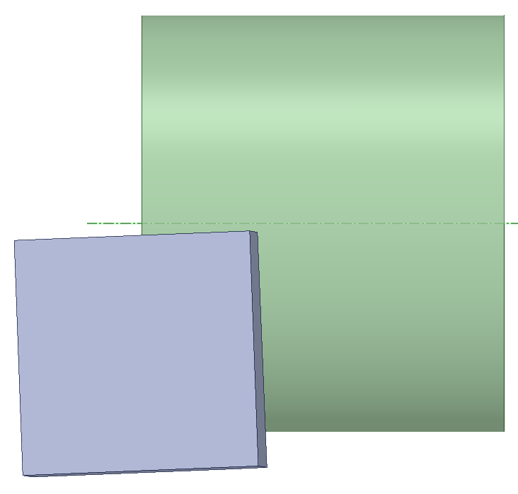
 Here is a 10 degree rake angle
 Here is a -10 degree rake angle
. Do you have access to a Research license? The mesh below has 250,000 nodes.September 22, 2020 at 2:23 amSubscriberThank you so much Sir for your reply. Now I will check by implementing This four different back rack angle value as your file in which you have set parameter for that. Yes sir My university has research license for that.
Thank you so much once again for always giving reply and motivating me to do this type of work ?
September 22, 2020 at 5:14 pmSubscriber.I made the workpiece into a Tube instead of a Rod to get better elements that had a larger characteristic length Mesh Metric than the mesh I made in the previous post.
To make the simulation take less time to compute, I increased the density of the materials by a factor of 100 which reduces the solution time by a factor of 10.
I also increased the rotational and translational velocity by a factor of 100 to reduce the end time of the simulation by a factor of 100 for a total reduction in wait time by a factor of 1000.
Unfortunately, these changes to the physics make material move in a way that it does not when using real density and real velocities and end times. The result was that the centrifugal force on the workpiece caused the material to expand radially and the Poisson's ratio made the length shrink faster than the tool advanced, so the edge of the workpiece moved away from the tool in the first 0.1 milliseconds of the simulation. It didn't help that when changing the end time, the tool advance distance ended up being 5e-3 mm instead of the intended 0.5 mm.
.
In the next iteration, I would reduce the velocities by a factor of 10, and increase the end time by 10, but increase the element size to recoup some of the extra simulation time that will entail. I would also insert an Initial Condition of the Velocity of the Tool. I forgot this on the attachment.
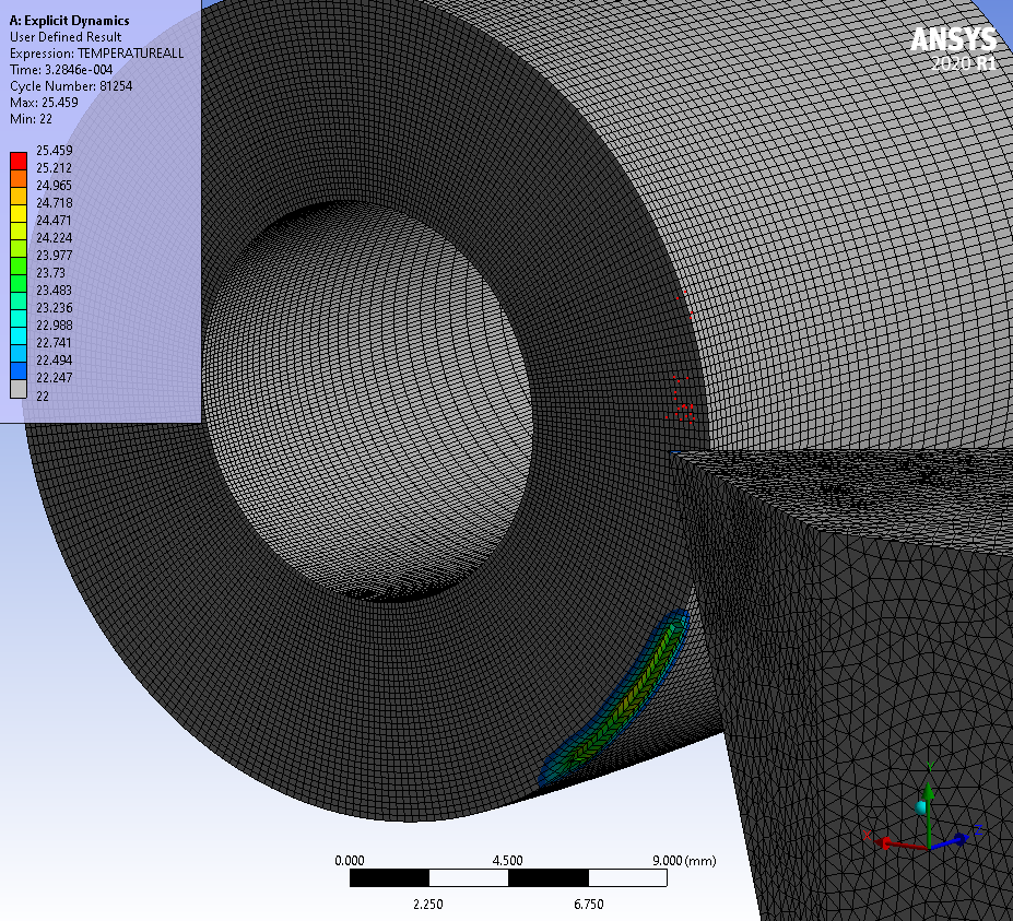
September 24, 2020 at 5:02 pmSubscriber.After about 25 degrees of rotation, the tip is starting to heat up. This ran for a few days on my 4-core computer, so you are going to wait a few weeks for one revolution. You might consider a coarser mesh to speed up the solution. Pay attention to the Mesh Metric Characteristic Length, which is at the bottom of the list. That is what controls the maximum time step.
.September 24, 2020 at 5:16 pmSubscriberI have so many doubt regarding your answer. So I am writting here this
1) Why are you select Tube instead of a Rod bcz both have different things after that simulation there are different value of temperature.
2) right now I am. Selecting material for Single point Cutting tool(HSS ) and Workpiece ( LM 6 which is one of grade for Aluminum alloy).
You have taken value for 100 multiple for original value for density and alll change the value for velocity for our simulation takes less time
But i can't understand your last Message which Is start from
" Unfortunately, these changes to the physics make ..! " Please highlight on that
Also please tell why are your selecting whole workpiece or whole tool you have select some faces so please tell regarding that
And can you please brief for reason behind this type of mesh . More highlight on mesh why are you select this particular mesh is there any reason/ physics behind this
September 25, 2020 at 1:44 amSubscriber1) The only reason to convert the geometry from a rod to a tube was to get elements with a larger Minimum Characteristic Length so that the solution would take less time to compute.
2) Use whatever materials you want for the two parts.
If you artificially increase density by a factor of 100, the solution will solve 10 times faster. This changes the physics because everything is heavier, but the stiffness didn't change. So if you are rotating by some angular velocity, the displacement will be 100 times greater.
I artificially increased the rotation speed and the translation speed to reduce the end time. I overdid this on the first attempt and the part changed shape too much, so I dialed back the artificial increase in speed, but that required the end time to be longer to get one rotation so the solution ended up taking weeks instead of days.
The time it takes to solve depends on the minimum characteristic length, the density, the modulus, the speeds and the end time.
September 25, 2020 at 9:31 amSubscriber.MAMIN219
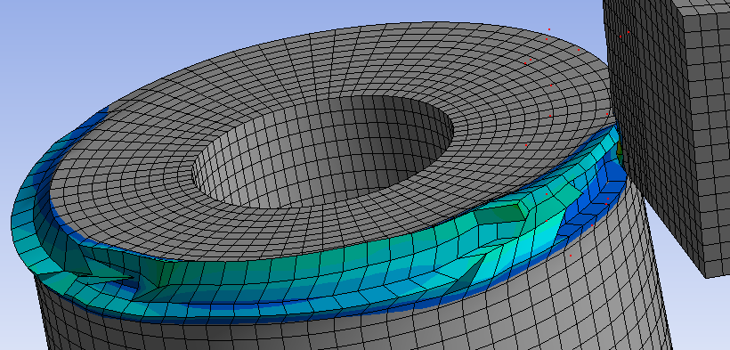
With larger elements, the simulation made 1/3 of a rotation in 7 hours so expect about 21 hours/rotation. Now you can get one rotation per day. The tip temperature has risen to 783 degrees C, but that is not really useful because the workpiece is rotating 10 times faster than it does in reality, so the temperature in this simulation is probably higher than the true temperature. Unfortunately, if you slow the rotational speed to the real speed, it may take 10 days to do one revolution instead of 1 day, and you probably need many revolutions to get the tool temperature up to a steady state.
. September 25, 2020 at 7:45 pmSubscriber
Thank you for your mail Array.
Respected Array Sir,
I want to clear my fundamental regarding these density for getting simulation rate faster and more knowledge on how can predict for suitable mesh for any Finite Element Analysis. In addition how to get near answer of Temperatures which is conceptual and also possible in reality.
Also Material Removal Rate is one the key features in Any Machining process so I want to understand MRR for This Turning process which will give some fruitful real in industry level.
Also my main concern is to learn what's going behind ansys means I want to learn this all things as analytical solutions for better understand like Matlab coding or like hand analytical calculations for understand "Heart of this analysis"
And for that i have to apply that on my main project .
So Can You please send me your mail id
Here I am also sharing my mail id with you so you can share you mail id in that
mihiramin319@gmail.com
Once again Thank you so much Sir for always continues reply and providing you valuable time with students to motivate and enjoy the better research skill in simulation and CAE field .
Regards
Mihir Amin
September 25, 2020 at 10:17 pmSubscriber.Dear Mihir Amin,
Thank you for those kind words. You are sharing your mail id not just with me, but the whole wide world. It's not necessary because we can communicate here MAMIN219 .
The MRR is a combination of the Turning Speed and the Feed Rate of the Tool. The Turning Speed depends on the workpiece diameter and the spindle RPM.
Here is a good discussion to help understand the Maximum Time Step, which has a lot to do with how many hours you will have to wait for the solution to compute.
Regards,
Peter
.September 26, 2020 at 9:24 amSubscriber.MAMIN219
While the larger elements allowed one rotation in one day of simulation, the elements were too large for the single point cutting tool to remove material in a meaningful way as you can see in the attached video.
. September 26, 2020 at 4:01 pmSubscriberRespected sir Array
Can you please explain like We are doing this simulation in ansys so can we get some nearer value like ex I am getting output of temperatures via thermal camera is 101 degree Celsius and also getting value of ansys temperatures value is like 90 degree or nearest to 105 or 110 degree like nearer to this value.
Or can we use other moving mesh to getting this results in simple manner.
I am also intended towards analytical approach for this too. Also please send analytical solution or Analytical Method to exactly how can we write FEM standard in hand with forumula base like whats the things behind ansys for feeling the heart of this results ?
In Addition I will send my file with you and my calculations of this end time. You will tell is my calculations for end time and all the things are correct like you
?
Thank you sir
September 27, 2020 at 11:41 amSubscriber.MAMIN219
My last attempt was to use more traditional rake angles than what you started with.

 Unfortunately, the elements are still too large to get good material removal.
 The tool tip is starting to erode and with the switch to hex elements on the tool, some hourglass defect has made its way into the mesh.
. I recommend you use Google to search for academic papers on single point cutting and see how researchers did this without using Explicit Dynamics. You can't do a study on Rake Angles if each setup takes a month to solve.September 27, 2020 at 1:19 pmSubscriber.
Thank you for your suggestions peteroznewman SIR,
with your advice I have tried Transient Structure analysis incorporate with APDL command in ANSYS 2020 R2 academic .I have put all the required things according to this attached thesis .I have not much more knowledge about APDL command and CONTA so I am trying this new things. Can you please help me in this. Is this correct approach towards Turning simulations.
Please highlight more on APDL command and send file with me for better understand,
.September 27, 2020 at 4:05 pmSubscriberThe Transient Structural analysis described in the 2016 Thesis has no material removal. There is only friction between the tool and workpiece generating heat as a function of the speed of rotation.
September 28, 2020 at 8:28 pmSubscriber.Thank you for your reply sir peteroznewman ,
Here I am attaching My ANSYS 2020 R2 file. Also I am putting here me calculations and all specification if there are any mistake please guide me.
1) I have taken Workpiece (Aluminum alloy LM6 material) and Single point cutting tool(HSS material).
2) I have defined Frictional contact between SPCT and workpiece and put 0.8 has frictional coefficient. and also go body interaction and put 0.8 as frictional coefficient. I have doubt in this : is there necessary to define frictional contact via manual contact region. or we have assigned body interaction and direct go type and assigned as frictional and put frictional coefficient. Please clarify this doubt and brief discussion this .
3) then I have used your previous mesh here. if any changes please guide me in details.
4) here I have taken Feed=0.4 & RPM=350
L=cutting length per min =feed*spindle speed=0.4*350=140 and so on.
here I am trying to move my Single point cutting tool as 20 mm
that's why i have taken displacement and in that for x =(0.0007 Depth of cut) and in z=(0.02 tool travel ) In addition in displacement 2 i have defined cylinder and coordinate geometry so i have taken Y= (17998.9718)
and i have found 8.5714 as my end time
i have also mentioned my logic behind value in y which is 17998.9718

Please give your feedback with explanation and mention any mistake or false procedure on it
thank you
Mihir Amin
.September 29, 2020 at 12:15 pmSubscriberPlease review this Wiki article on Feeds and Speeds. https://en.wikipedia.org/wiki/Speeds_and_feeds
Your document uses the word feed in an equation with RPM, which is wrong. Cutting Speed uses RPM and the diameter of the workpiece in an equation to calculate the tangential surface speed of the material being cut.
Feed Rate is the velocity that the tool tip has along the axis of the workpiece.
The depth of cut together with Cutting Speed and Feed Rate determine the Material Removal Rate.
Different materials have different cutting speeds that work best for them. https://www.cnclathing.com/guide/cutting-speed-chart-for-different-materials-in-turning-drilling-and-more-cnc-machining-processes-cnclathing
September 29, 2020 at 1:50 pminouzil
Subscriber.Greetings,
peteroznewman Sorry to crash in on the discussion. I am facing a problem in my 2D simulation and would greatly appreciate your input. In my 2D simulation for Inconel, I am unable to get the temperature distribution on the tool. I have defined the tool with flexible stiffness, thermal property and plasticity model. I added the temperature through the worksheet after the simulation. But it always only gives the temperature distribution on the workpiece. Not the tool. What am i doing wrong? I have also attached images of the material properties and the .wbpz file. Would greatly appreciate your support.
This is the link to the actual post: /forum/discussion/15835/missing-tool-temperature-distribution-2d-explicit-dynamics#latest
{"embed-error":true}


 Gratitude for the support.
Regards
Ibrahim Nouzil
.September 29, 2020 at 7:00 pmSubscriber.peteroznewman
Respected sir,
1)I have defined Frictional contact between SPCT and workpiece and put 0.8 has frictional coefficient. and also go body interaction and put 0.8 as frictional coefficient. I have doubt in this : is there necessary to define frictional contact via manual contact region. or we have assigned body interaction and direct go type and assigned as frictional and put frictional coefficient. Please clarify this doubt and brief discussion this .
2) I have applied angular velocity as 36.56 (for N=350 RPM) AND velocity as 0.421( using formula pi*D*N/60 AND N=350,DIAMETER 23 MM for cylinder ) and end time i have calculated my last conversion photo and conversion. I am also mentioning regarding link from which i have calculated my end time for 20 mm tool travel length
3)
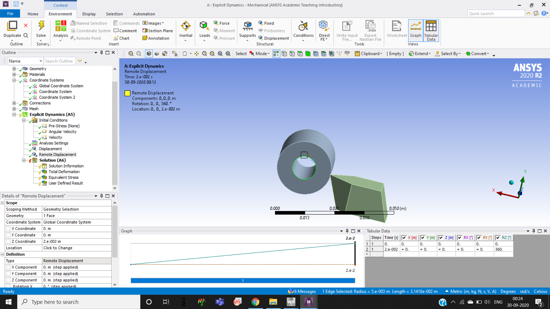 this is your snapshot from your second file .please give me your guidance regarding my parameter so what are those values on remote displacement which i should give to run this file .and also tell which face i should select for this remote displacement.
Please give your feedback with explanation and mention any mistake or false procedure on it and send your corrected file with me for better understand .
Thank you .
.October 1, 2020 at 4:25 pmSubscriberRespected SirArray ,
I have sent my file and my list of doubt with you. Please help me as soon as possible so that i will start some brief in this
Thank you sir
Mihir amin
October 2, 2020 at 12:09 pmSubscriber.1) It is not necessary to define Frictional Contact. That only works on the surface. The Body Interaction has the friction. That works as the surface is removed.
2) What was your reference for selecting the surface cutting speed?
Whenever you write a number, always write the units after it.
The image below used a rigid tool (which is not useful for you) and took 4 days (96 hours) of computation on a 4-core computer for less than 1/8 of a revolution. I don't see how you are going to have time to study multiple angles on the tool, where several rotations will be required to get the tool tip up to a steady state temperature unless you have access to a much faster computer with 16 (or more) cores .
. October 3, 2020 at 7:13 pmSubscriber.
peteroznewman Thank you for your reply
We have research licensed in my university and I am not in hurry
let me tell my doubt point wise
1) What is the logic behind giving 360degree in that tabular data
2)So according to my parameter as mentioned in the previous post ( have applied angular velocity as 36.56 rad/sec (for N=350 RPM) AND velocity as 0.421m/sec ( using formula pi*D*N/60 AND N=350,DIAMETER 23 MM for cylinder ) and end time i have calculated my last conversion photo and conversion. I am also mentioning regarding link from which i have calculated my end time for 20 mm tool travel length) what value i should give ?

 3)Please brief explain regarding your value in past discussion file .I am uploading Screenshot(ABOVE)
you have also given velocity in your second file so according to our parameter we calculated the cutting speed and gave velocity to the tool
4) I am not able to move single point cutting tool by 0.7 towards workpiece which is in x direction according to my global coordinate(which is 0.7 mm [depth of cut])
so please change this in file so that we will directly do our simulation and highlight brief explanation for better understand.
Sir please
make require changes so that i only have to run these file
.October 3, 2020 at 10:57 pmSubscriber.1) In my model, I put a 360 degree rotational displacement to solve exactly one rotation. By choosing the end time, that defined an initial condition for rotational velocity, which I applied (in rad/sec) to the body. You will need more than one revolution, so use an applied rotational velocity instead of a rotational displacement, that way, you can change the end time without worry.
2) I gave you a reference to metal cutting speeds and asked you what cutting speed (SFM) you had chosen.
 When you specify the RPM, you must check that the SFM is within the acceptable range for the material, is it?
 Feed Rate is the velocity of the tool along the axis of the workpiece. You have to decide on the distance you want to advance the tool on each revolution. Your handwritten note showed you wanted to advance 20 mm in 50 revolutions or a feed of 0.4 mm/revolution. That will leave a rough surface. Here is the calculation of the tool velocity and end time.
 3) The guidance is that the Initial Velocity of the Tool and the Velocity BC on the tool have to match (14.661 mm/s) and the Initial Angular Velocity and the Angular Velocity BC on the workpiece have to match, 36.652 rad/sec = 2100 degrees/sec.
. I am using the free version of PTC Mathcad Prime to keep track of the units and perform calculations without mistakes.October 4, 2020 at 12:04 amSubscriberArray
I see you upgraded to ANSYS 2020 R2. I only have access to ANSYS 2020 R1 for large models, so I wasn't able to open your model.
Please post a New Discussion to ask any new questions.
Good luck!
December 22, 2020 at 10:17 amcncdrilling
Subscriber.We- blacksmith CNC are known for a manufacturer, exporter, and trader-a wide range of premium quality
 CNC drilling machine. The product range offered by us is standard quality. This CNC drilling machine is highly welcomed among our customers for their user-friendly operation, low power consumption, low maintenance, and optimum performance. We equip with the latest machinery. It helps us in executing advanced technologies to manufacture these machines.
Computer Numerical Control (CNC) drilling machine commonly implement for mass production. A variety of semi-automated drilling machines are also available in the market. It’s a meaningful benefit that CNC drilling machines are capable of receiving many items.
We have been able to provide huge customers across the world, owing to our transparent transaction policy, ability to a customer-centric approach. Being a reputed name of this field, we assure you that the premium quality of the offered machine is never compromised.
.August 25, 2021 at 3:53 ambomei
Subscriber.Thanks for sharing. If you need CNC service from China, please contact us, we will provide you 24 hours. https://stbomei.com/
.April 19, 2022 at 2:46 amChinamfg
Subscriber.You don’t have to sacrifice quality for speed anymore. Be-cu can rapidly manufacture aluminum parts with precision tolerances as tight as +/- 0.0001 in via 5 Axis Machine.
As one of famous Aluminum CNC Machining manufacturers from China, Be-cu aluminum machining china company has own specialized technical staff and management team to design as your custom draws and samples, we have rich experience and understand each type of the Aluminum material characteristics. So we can offer you the best machining aluminum solution according to your requirements of Aluminum parts and components.A variety of machines offer 5-axis, 3-axis, and 4-axis functionality. See prototype features below
- Volume: 1-20 or more parts
- Estimate: within 24 hours
- Lead time: 3 days minimum;100000+machined parts each month
- 100+CNC machines,Hand Metrology, Laser & CMM Inspections
- Standard tolerance: +/- 0.1mm
We have been a quick-turn and reliable online manufacturer and supplier for more than 30 years and we are an ISO 9001:2015 & ITAF 16949 certified aluminum cnc machining expert, always bringing demanding and OEM aluminum parts with high accuracy and precision.Creating precision aluminum components with an outstanding surface finish is possible with our aluminum cnc machining capabilities.No matter how complex the aluminum parts, each step will be executed with a rigorous attitude, to deliver exceptional aluminum cnc machining components that demonstrate the highest quality standards. Even though any problems during the process, we’ll keep running the job and make adjustments until all the issues are addressed. If you require a well-established and cost-effective aluminum cnc machining company to take over your project, Be-cu can achieve your expectation.If you are willing to work with us or want to know more details, welcome to contact us via email..
.Viewing 28 reply threads- The topic ‘Regarding How to change multiple back rack angle in turning simulation’ is closed to new replies.
Innovation Space Trending discussions
 Top Contributors
-
peteroznewman
 5149
5149 -
scabo
 1831
1831 -
Dennis Chen
 1387
1387 -
javat33489
 1248
1248 -
Shyam Prasad V Atri
1021
Top Rated Tags
© 2026 Copyright ANSYS, Inc. All rights reserved.
Ansys does not support the usage of unauthorized Ansys software. Please visit www.ansys.com to obtain an official distribution.
-


