-
-
January 11, 2024 at 4:27 am
ANUPAMA
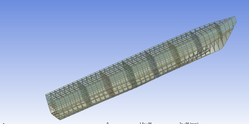
SubscriberHai, I am writing to seek your assitance regarding ansys analysis. Iam trying to do a finite element analysis in ansys mechanical. i have modelled a ship with longitudinal girders, trransverse frames and bulkheads. I will attach my model below.
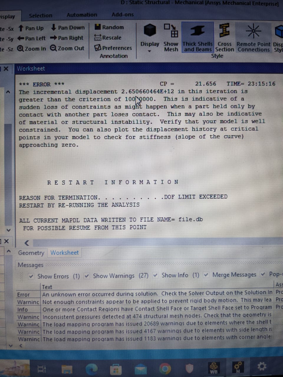
I have to find out the pressures and motions acting on the ship due to waves. I have found that using ansys aqwa. And mapped the results to ansys mechanical. I have used the hydrodyanmic pressure tool from ansys mechanical to apply these results to ansys mechanical. But applying i have got errors such as "an unkown error occured view solver output in solution information. I have applyed the boundary condtions through remote points. I have given hydrodynamic pressure and standard earth gravity. But no luck!!! If i suppress the hydrodynamic pressure tool then there were no errors.
I don't know the reason. Kindly help me to fix this probelm. Iam working on my final project.
Thanks in advance.
-
January 11, 2024 at 3:14 pm
Mike Pettit
Ansys EmployeeHello,
Are there any other warnings or errors in the Messages window? What does your Commands (APDL) script contain?
Mike
-
January 12, 2024 at 5:09 am
ANUPAMA
Subscriber -
January 12, 2024 at 11:17 am
Mike Pettit
Ansys EmployeeThanks. I suspect that the bodies making up the vessel are not all connected together, so some of them are flying off into space when you apply the Hydrodynamic Pressure.
To test this, I would recommend the following:
- suppress the Hydrodynamic Pressure and Commands objects;
- add Standard Earth Gravity to the analysis (note that the Hydrodynamic Pressure object automatically includes gravity if the hydrostatic pressure component is included);
- turn on the Weak Springs option in the Analysis Settings;
- re-run the analysis;
- plot the Total Deformation of the vessel.
You may find that one or more bodies do not stay attached to the rest of the vessel when you review the deformation result. If this is the case, you should either:
- modify the geometry so that all bodies are grouped into a single component, with shared topology; or
- turn on Batch Connections (Mesh Based Connection option) in the Mesh settings, and add a Connect operation to the Mesh with all bodies selected.
I hope this helps!
Mike
-
March 5, 2024 at 8:48 am
Abdul Haq
SubscriberDear Author,
I am Abdul Haq from Southeast University. I am currently doing my masters and my research is the same as your research, Ship analysis based on finite element and I am using LS-DYNA for my research.So can we discuss? I need the ship's model for my research.if you read my replyplease give me your email or phone Whatsapp number -
March 5, 2024 at 8:49 am
Abdul Haq
SubscriberDear Author, I am Abdul Haq from Southeast University. I am currently doing my masters and my research is the same as your research, Ship analysis based on finite element and I am using LS-DYNA for my research. So can we discuss? I need the ship's model for my research. if you read my reply please give me your email or phone WhatsApp number
-
January 12, 2024 at 2:36 pm
ANUPAMA
SubscriberHai,
Thank you for your response..I will try with that.
But could you please tell me how to group all these components together.Because here I have added T sections and transverse frames. So how to unite all these components?
Thanks in advance.
-
January 16, 2024 at 4:26 am
ANUPAMA
SubscriberHai,
I have turned on the "batch connection and added a connection group with all bodies selected. But the meshing operation become failed. This operation generates a failed mesh.
So how can I unite all bodies together?Kindly help me to fix the problem.
Thanks in advance
-
January 17, 2024 at 5:35 pm
Mike Pettit
Ansys EmployeeHello,
This depends on whether you are using DesignModeler or SpaceClaim as the geometry editor.
In DesignModeler, select all of the bodies in the Tree Outline, then right-click and Form New Part. Click on the new Part, and in the Details View confirm that the Shared Topology Method is set to 'Edge Joints'.
In SpaceClaim, select all of the bodies in the Structure tree, then right-click and Move to New Component. Click on the new Component, and in the Properties panel change the Share Topology option from 'None' to 'Share'.
Then re-import the geometry into the Mechanical editor.
I hope this helps.
Mike
-
-
January 18, 2024 at 8:38 am
-
January 18, 2024 at 9:24 am
ANUPAMA
SubscriberHai,
I have re-run the analysis. Now I am getting maximum von-mise’s stress at lower hull. But considering ship as a beam it should occur at upper deck and in midship. But my stress distribution is not like that.
Similarly I have given boundary conditions as shown below. I have given remote boundary displacements through remote points at aft and forward end. If i remove the fixed support here the connections have lost and the bodies get separated. How can i give boundary conditions for a complex ship like this without loosing connection?
Also If there are some connction issues to components of ship.The connection between stiffeners and deck have lost while analysing. Kindly help me to fix this problem.
-
- The topic ‘Regarding finite element analysis’ is closed to new replies.


-
2979
-
970
-
857
-
755
-
599

© 2025 Copyright ANSYS, Inc. All rights reserved.


