TAGGED: aedt
-
-
December 27, 2024 at 10:16 pm
michaelpmarquez
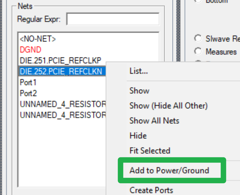
SubscriberHow do you determine the reason why certain nets are listed in red font in the Nets panel in AED? Right clicking on them doesn't provide any information. If they were errors I would assume they would be shown when running from the main menu Layout>Nets>Select All Net Violation.
-
December 30, 2024 at 3:10 pm
-
December 30, 2024 at 11:32 pm
michaelpmarquez
SubscriberYang thank you for the response. I have a follow up question. If the design is an imported Allegro .brd file how does AED determine which nets to automatically assign to the Power/GND nets? It doesn't seem to be based on whether the Net Type in Allegro is set to Signal vs. Power or whether the Net Class is set to PWR or None. It seems to mainly classify copper pour regions it sees in the .brd file as Power/GND but I noticed that it doesn't classify all copper pour regions as such. The only other criteria I can see is it is based on a parsing of the net name to figure out it is a power/GND net when it finds net names such as "1P3_SUPPLY_A" or "1V35" but it also seems to classify nets with names such as "SYNC", "TX1A_N", "UNNAMED..." as power/GND as well.
-
December 31, 2024 at 2:46 am
Yang Zhao
Ansys Employee-
December 31, 2024 at 10:44 pm
michaelpmarquez
SubscriberYang thanks again
-
-
- You must be logged in to reply to this topic.


-
3442
-
1057
-
1051
-
917
-
896

© 2025 Copyright ANSYS, Inc. All rights reserved.


