TAGGED: compressor, fluent, porous-zone, udf, udf-fluent
-
-
October 26, 2021 at 4:12 pm
sebastiancg26
SubscriberHi everyone!
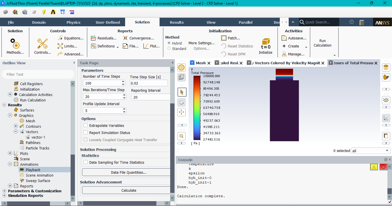
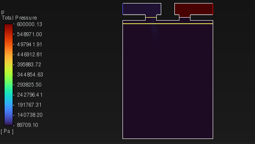
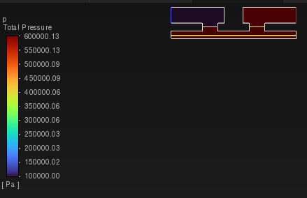
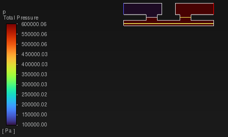
Currently, I'm simulating the transient behavior in a reciprocating compressor. For this, I implemented the use of a UDF to open or close the compressor valves through Porous Zone (Changing the viscous resistance) based on a average pressure. This code works great, but the problem is that in the animation of total pressure, the behavior of that pressure is totally uniform, wich doesn't make sense. I would like to ask you if anyone of you knows what is causing this problem and how I can fix it?
October 26, 2021 at 7:08 pmOctober 27, 2021 at 10:46 amRob
Forum ModeratorWhich solver licence are you using?
October 27, 2021 at 4:57 pmsebastiancg26
SubscriberAnsys Student
October 28, 2021 at 10:47 amRob
Forum ModeratorHas the model run for long enough to see a change, and converged each time step?
October 28, 2021 at 1:53 pmsebastiancg26
SubscriberOf course Rob, I've tried many things, but I still can't find any solution..
October 28, 2021 at 4:05 pmRob
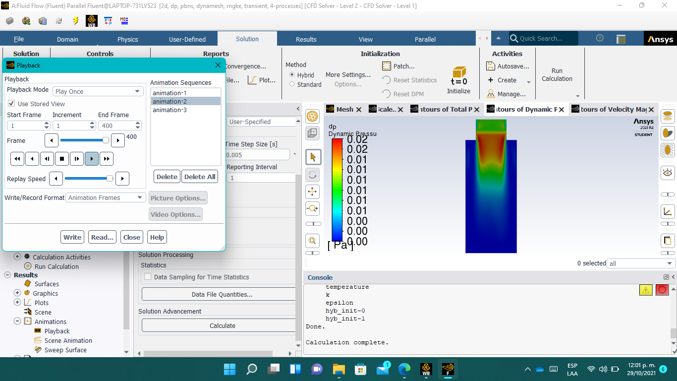
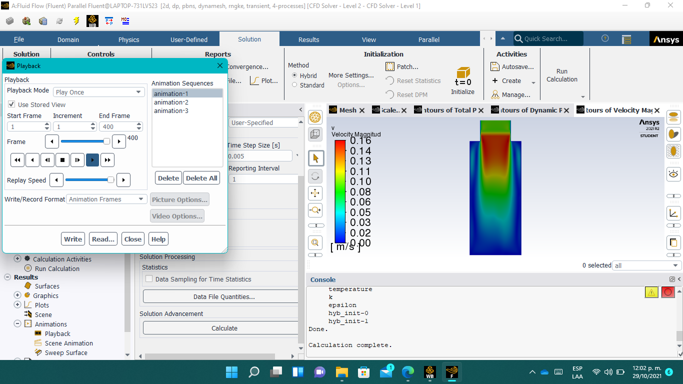
Forum ModeratorCan you plot some more data, eg velocity. Diagnosing from one plot with no idea about what else is set is difficult.
October 29, 2021 at 5:03 pmsebastiancg26
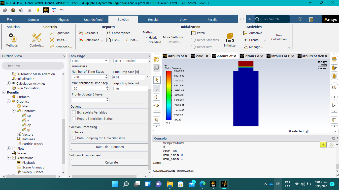
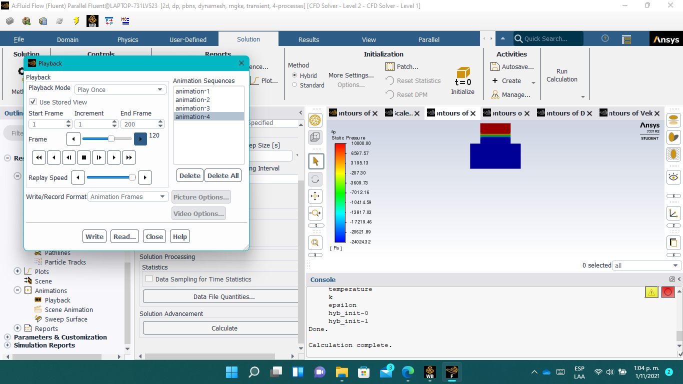
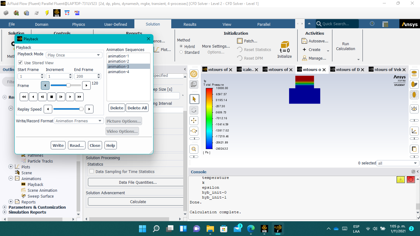
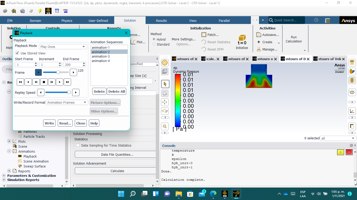
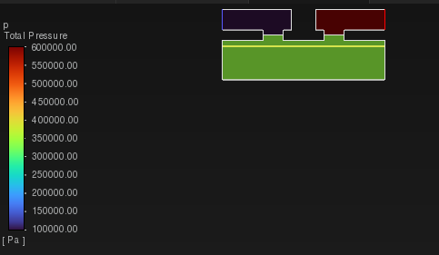
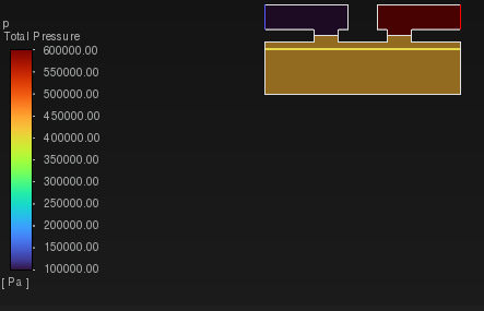
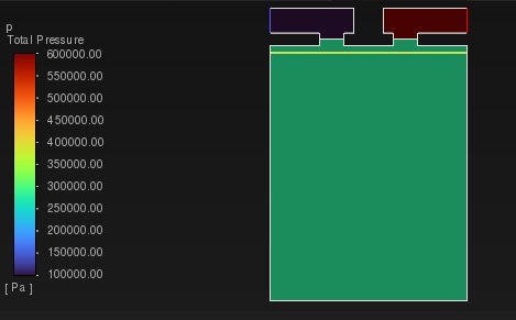
SubscriberSure. When I plotted velocity, I realized that the velocity values throughout the simulation were quite low, thus, the Dynamic Pressure values had the same behavior. For this reason, the dynamic pressure values aren't enough to modify the Total Pressure behavior. Next, I will leave the screenshots of Total pressure, Dynamic Pressure and Velocity plots.

November 1, 2021 at 1:29 pmRob
Forum ModeratorAnd you're using superficial velocity in the porous media. Check static pressure too. I suspect the dP over the porous media is masking the results as the scale is very big.
November 1, 2021 at 2:06 pmsebastiancg26
SubscriberNovember 1, 2021 at 4:37 pmRob
Forum ModeratorYes. Now replot with a range of 0Pa to about 20k Pa.
November 1, 2021 at 5:01 pmsebastiancg26
SubscriberIt had the same result..
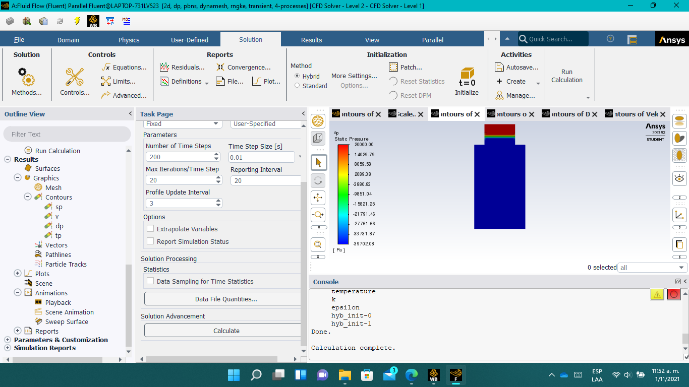 Theese simulations are just an example, I have been simulating with only one boundary condition (Inlet pressure=100kPa), and the porous media is configured like this:
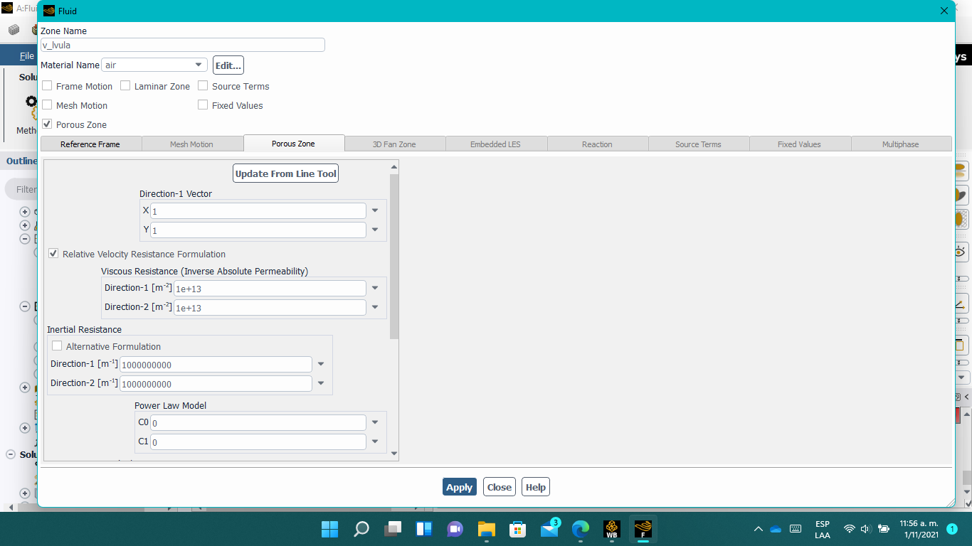 As I mentioned you, the idea is that the viscous resistance coefficent changes according the pressure in UDF (wich is already finished, and works well), however, now I have been running a series of test to determine the proper porous media setting..
November 1, 2021 at 5:06 pmRob
Forum ModeratorTry a lower upper limit. Simply, the pressure field is being hidden by the dP over the membrane.
November 1, 2021 at 6:05 pmNovember 2, 2021 at 11:45 amRob
Forum ModeratorNo need to use alternative. The solver is calculating the flow based on your settings. The porous coefficients are high, so the pressure loss all occurs at the membrane. Depending on the upstream boundary flow must pass through the membrane.
November 2, 2021 at 7:22 pmsebastiancg26
SubscriberI need to establish a coefficient that guarantees a total flow (that simulates an open valve) and a coefficient that guarantees the blocking of the flow (that simulates a closed valve), without affecting the behavior of the pressure field in the cylinder. How I can do it? Thanks for all your comments..
November 3, 2021 at 9:30 amRob
Forum ModeratorPorous media will cause a pressure drop, depending on the external boundary conditions and other flow features it can't stop the flow. That's why the IC tools allow a crank angle activation of TUI commands: we switch surfaces from interior to wall.
We model oil reservoirs with porous media, with 3-400bar behind the system anything will move!
November 3, 2021 at 4:18 pmsebastiancg26
SubscriberSo.. Can I switch a surface from interior to wall depending on the pressure instead of the time?
November 3, 2021 at 4:46 pmRob
Forum ModeratorNot without some horrible UDF scheme calls.
November 3, 2021 at 6:07 pmsebastiancg26
SubscriberHow can I do theese scheme calls?
November 4, 2021 at 12:22 pmRob
Forum ModeratorWith a UDF. Unfortunately if it's not in the UDF manual we can't offer any assistance. Simply, you're making a call to the solver based on a value that the UDF calculates, this isn't straight forward.
November 4, 2021 at 1:20 pmsebastiancg26
SubscriberWhat a pity.. So, is there any other way to simulate a flow block?
November 4, 2021 at 3:45 pmRob
Forum ModeratorGiven it's a piston compressor why not base open/closed on the time?
November 5, 2021 at 5:19 amsebastiancg26
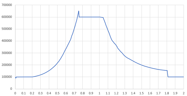
SubscriberThis simulation is carried out through "Events"- The events are:
Delete Sliding interface at 0.2 [s] to closing inlet valve.
Create Sliding interface at 0.75 [s] to opening outlet valve.
Delete Sliding interface at 1 [s] to closing outlet valve.
Create Sliding interface at 1.8 [s] to opening inlet valve.
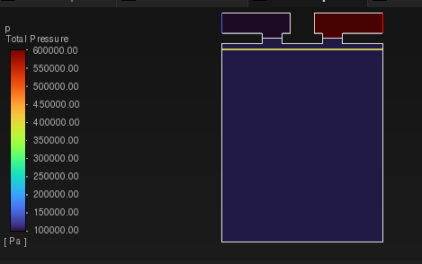
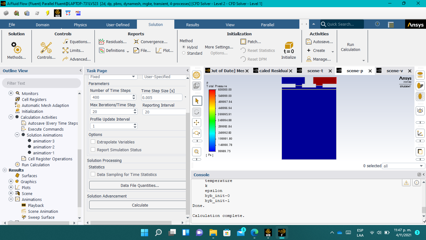
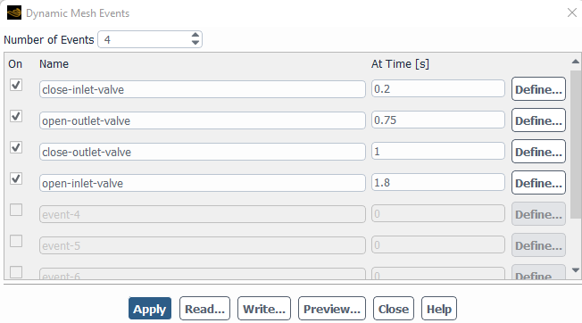 But, the pressure behavior remains the same, it's constant. Why this?
November 5, 2021 at 12:29 pmRob
Forum ModeratorHave the commands executed? What does the TUI transcript report?
November 5, 2021 at 3:18 pmNovember 8, 2021 at 12:27 pmRob
Forum ModeratorIf the graph is as above, what are you displaying to not see it in the contours?
November 9, 2021 at 5:39 amsebastiancg26
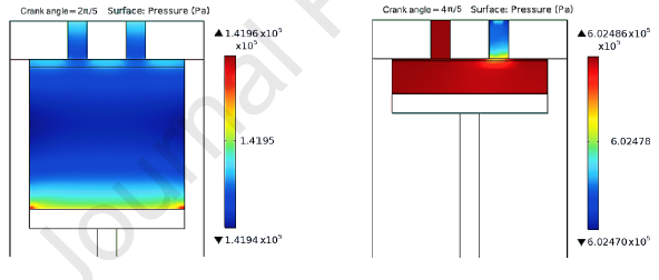
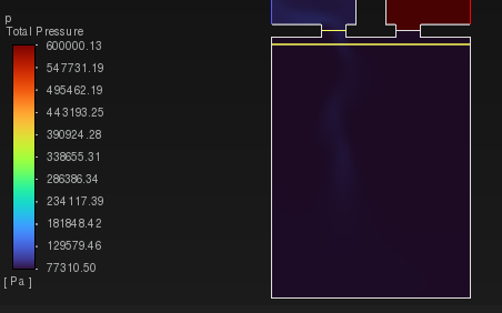
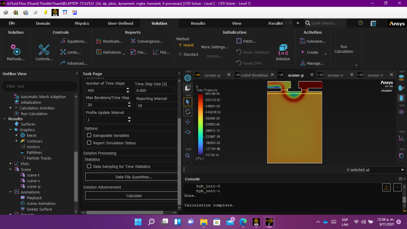
SubscriberActually, I don't know.. however, if the simulation runs without events, it does show a pressure distribution. When the simulation runs with events, the pressure behavior seems constant throughout the area, as I showed you in the images in previous comments.. I clarify that the only modification I made between the two simulations was adding / removing the events. The rest of the configuration remains the same..
This a plot of the pressure behavior in a simulation whitout events..
November 9, 2021 at 1:39 pmRob
Forum ModeratorEvents are things changing, so will alter the result. If you display with a large scale/range on the plots subtle differences in the flow may be missed.
November 9, 2021 at 2:54 pmNovember 9, 2021 at 4:11 pmRob
Forum ModeratorThat looks like they're using crank angle to drive the solution: exactly how you've done. However, as you've only shown one graph and an image at the "piston down" it's hard to see what is/isn't working.
November 11, 2021 at 5:12 pmNovember 11, 2021 at 5:26 pmRob
Forum ModeratorThat looks like the interface creation is doing something weird. Try switching to SIMPLE and use PRESTO!
November 11, 2021 at 7:46 pmNovember 12, 2021 at 12:16 pmRob
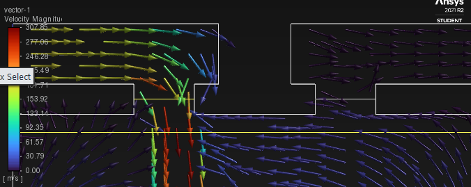
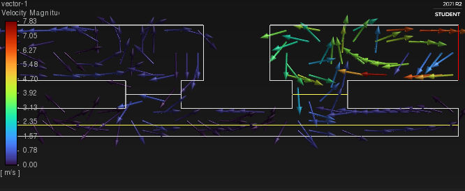
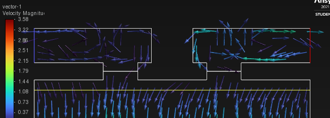
Forum ModeratorAlmost certainly the interface then. The solver setting change was to confirm they weren't to blame. Focus the view around an interface and look at the velocity vectors. Using fluxes see how much mass is passing though an "open" valve.
November 12, 2021 at 1:45 pmsebastiancg26
Subscriber
November 12, 2021 at 1:45 pmNovember 12, 2021 at 4:19 pmRob
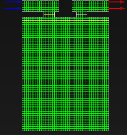
Forum ModeratorYou also have moving mesh, are you accounting for the volume change too? Please can you post an image of the mesh? Or did you skip several vectors in the plots?
November 13, 2021 at 2:25 pmNovember 15, 2021 at 2:30 pmRob
Forum ModeratorMake the mesh a lot finer at the top (and overall) and see what happens.
November 17, 2021 at 4:56 amsebastiancg26
SubscriberThat did not influence the effects.. I made a new 0.5 mm quadrilateral mesh, and I changed the step size to 0.0001 s
November 17, 2021 at 2:06 pmsebastiancg26
Subscriberthe turbulence model has something to do with it? I use k-w model..
November 17, 2021 at 2:52 pmRob
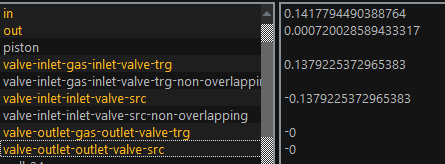
Forum ModeratorDoubt it. Monitor flow in, flow out and piston volume. Also monitor the flow over the 3 interface pairs. We should see the latter give a zero result at various points, and if so the inlet/outlet ought to be around zero then too.
Viewing 42 reply threads- The topic ‘RECIPROCATING COMPRESSOR VALVES – POROUS ZONE MIMIC’ is closed to new replies.
Ansys Innovation SpaceTrending discussionsTop Contributors-
3387
-
1052
-
1050
-
886
-
857
Top Rated Tags© 2025 Copyright ANSYS, Inc. All rights reserved.
Ansys does not support the usage of unauthorized Ansys software. Please visit www.ansys.com to obtain an official distribution.
-

