Ansys Assistant will be unavailable on the Learning Forum starting January 30. An upgraded version is coming soon. We apologize for any inconvenience and appreciate your patience. Stay tuned for updates.
General Mechanical

General Mechanical

Topics related to Mechanical Enterprise, Motion, Additive Print and more.

Reaction Forces to Balance the Moments of a Lever Mechanism.

    • zabee.k
      Subscriber

      Hello Forum,

      I have a Lever Mechanism in which i wanted to understand how much of force is needed to lift the lever. I did the RBD Analysis for this but the thing is, if i give displacement boundary condition for a certain time period the reaction forces are higher then the theoretical calculations. What i have understood is the reaction given by solver are to achieve the displacement over the given time period.

      Is there a way in which i can understand the reaction forces needed just to balance the lever as it lifts. One way of doing is performing a static analysis for specific orientation of lever and getting the reaction forces, but that time consuming. How can i do this in MBD Software.  

      Just for the clarification, When the lever is at initail condition, i calculated the moments and thus reaction force needed is around 30KN and as it lifts up, it reduces and for the final position the reaction forces are 17KN. But if i give displacement boundary condition in MBD and try to see the reaction forces, the reaction forces are constant without any change in it. Is my understanding correct? These reaction forces are to maintain the motion and not just enough to balance the moment. How do i get reaction forces to balance the moments in MDB. (Preferably Ansys Motion).

      Thanks

    • peteroznewman
      Subscriber

      Hello Zabee,

      Please reply with images that show the lever, the displacement or force boundary conditions and your hand calculation for what you expect for results.

    • peteroznewman
      Subscriber

      Hello Zabee,

      I am learning Motion, so there may be a way to get what you want using that, but I don't know how. If you use a dynamics solver, you have to move things slowly to keep inertia forces insignificant. I know one way to get what you want that delivers a pure statics solution.

      Use SpaceClaim Assembly constraints to define the mechanism and create an input parameter to pose the mechanism at different angles of the lever. Use Static Structural to solve for the reaction force to support the pivot at the top of the lifing link in that pose and make the force an output parameter. Finally, use the Workbench Parameter Set: Table of Design Points, to step through a set of input angles and compute the reaction force to draw a graph from the data in the table. One click on Update All Design Points will automatically fill out the table.

      This example has two links with the following three joints. The In-Line joint allows the top pivot to slide along the local Z direction and leaves the rotations free.

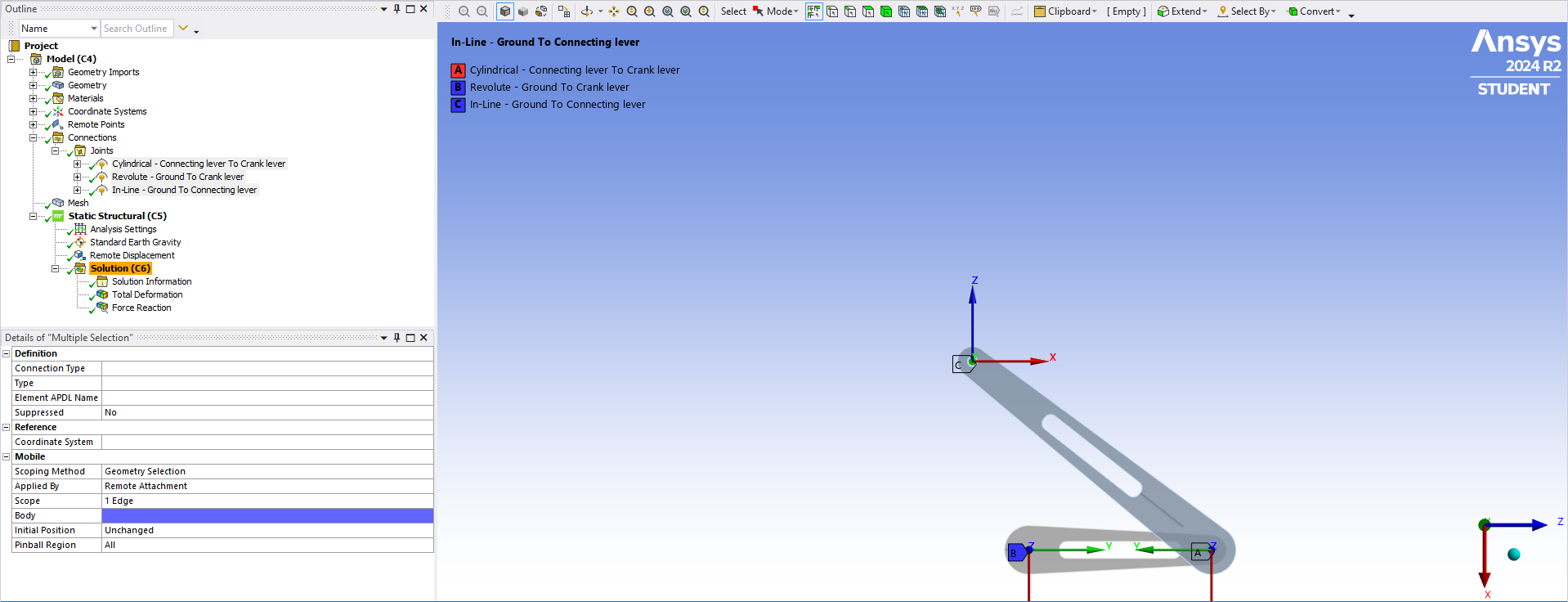
      A remote displacement has global X (local Z) set to 0 at the top pivot and the reaction force is output.

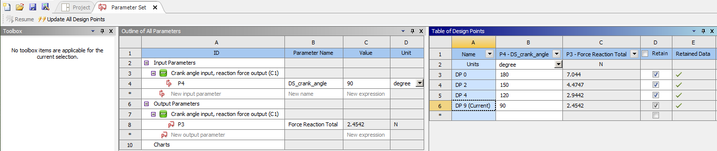
      Here is the Table of Design Points with the input angles to pose the mechanism and the output Reaction Forces.

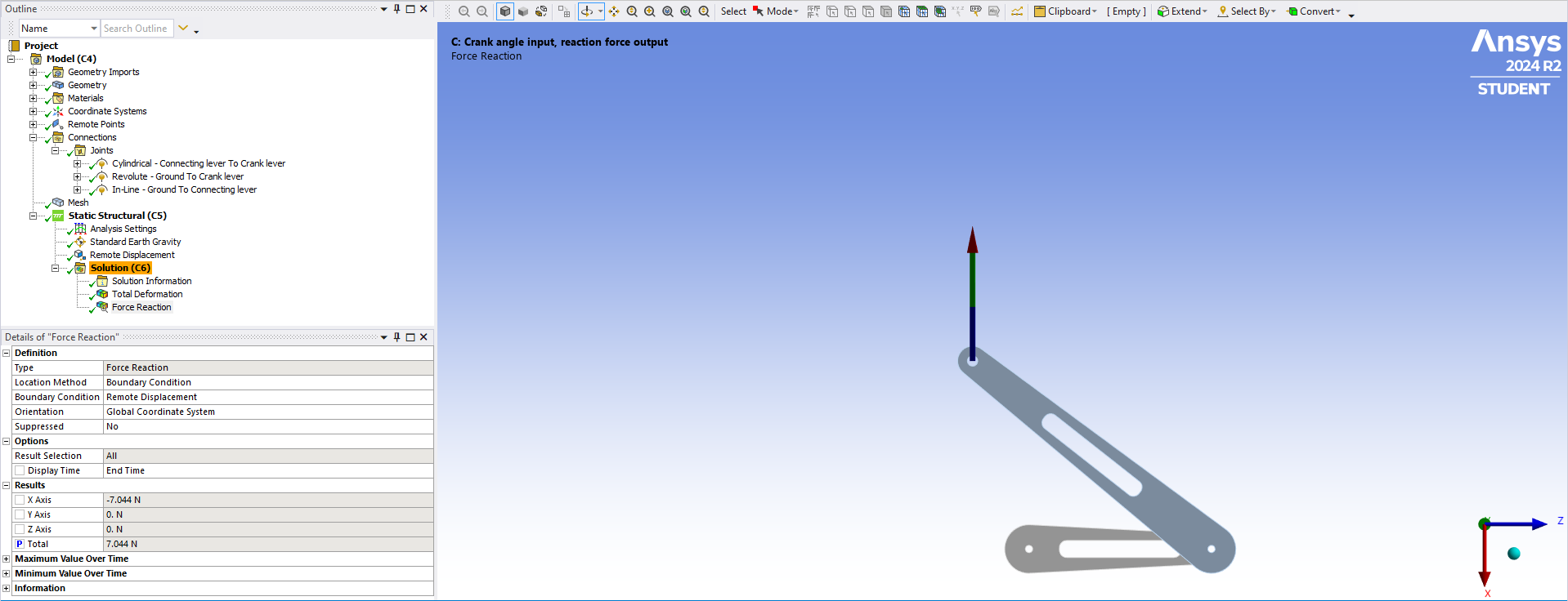
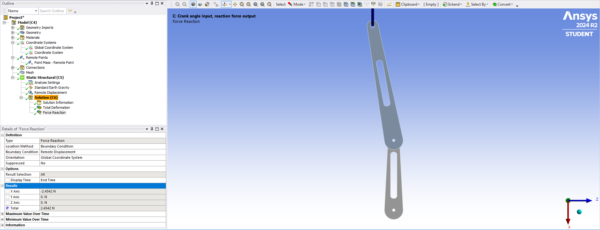
      Here is the final angle in the table.

      SpaceClaim was difficult to create the input angle parameter.  It may be simpler in Design Modeler.

      • zabee.k
        Subscriber

        Hello Peter,

        Yes, we are getting the forces needed to balance out the moments by running a dynamic anlysis with slower speed. 

        Thanks you for your support and suggestion.

Viewing 2 reply threads
  • You must be logged in to reply to this topic.
[bingo_chatbox]