

-
-
December 19, 2020 at 2:58 pm
rkoomul
SubscriberDecember 19, 2020 at 10:11 pmpeteroznewman
SubscribernYou have some helpful images in the attached pdf. Unfortunately, none of the ANSYS staff can see them because they are not permitted to download attachments.nI recommend you paste the contents of your pdf into a post and insert the image directly into the post.nDecember 20, 2020 at 2:59 pmSubscriberThank you peteroznewman for the comments. Here are the main contents (omitted a few figures) of the PDF file that I uploaded earlier. n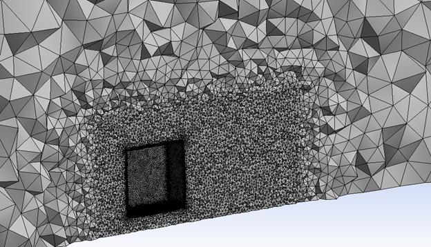 Mesh on a cutting plane through the body. The body inside the computational domain is of size 0.2x0.2x0.2m and is 0.05 m above the ground. The mesh contains approximately 0.5 million nodes and 1.85 million elements. A “body of influence” was used for refining the region around the body and the wake.n n
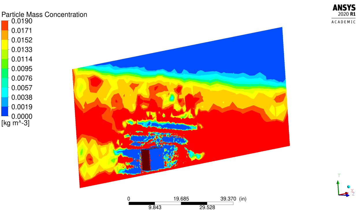 DPM particle concentration on the cutting plane. The inlet was specified as “velocity inlet” with a velocity 40 m/s and the outlet was specified as a “pressure outlet”. The ground, top, and sides were specified as slip walls. Intensity of the rain was taken as 19 gm/m^3 (moderate rain) and droplet sizes were assumed to vary from 1mm to 3 mm. The terminal velocity of the droplets was taken as 7.9 m/s. The injector was specified at the inlet surface with a DPM particle velocity of 40 m/s along the x-direction and -7.9 m/s along the y-direction. The mass flow rate was specified based on the rain intensity. Issue: DPM concentration is zero at some part of the domain in front of the block, where there is a change in the mesh resolution. This is supposed to be uniform, since there is no obstructions in front of the body.n
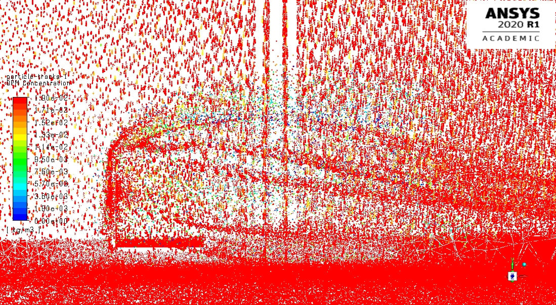 Particle tracks visualization from Fluent. Figure shows particles are moving uniformly in front of the block and get reflected from the ground and the body. For DPM, “wall-film” boundary conditions were used for both the body and the ground, and “escape” boundary conditions were used for other boundaries.n
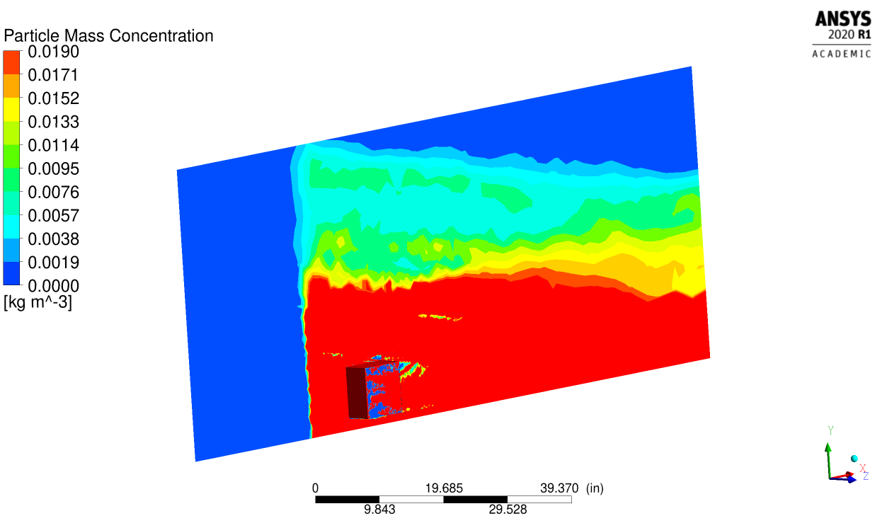 Particle mass concentration when the rain droplets were injected from the middle of the domain, where the refined mesh starts. All other parameters are kept the same as the injection from the inlet surface. Issue: Even though uniform distribution is specified for the injector, the concentration is high at the fine mesh region and low at the coarse mesh region.nThe most important issue is the predicted drag coefficient is the same for all three different cases (no rain, rain droplets injected at the inlet, and rain droplets injected in front of the body).n
December 22, 2020 at 9:29 pm
Particle mass concentration when the rain droplets were injected from the middle of the domain, where the refined mesh starts. All other parameters are kept the same as the injection from the inlet surface. Issue: Even though uniform distribution is specified for the injector, the concentration is high at the fine mesh region and low at the coarse mesh region.nThe most important issue is the predicted drag coefficient is the same for all three different cases (no rain, rain droplets injected at the inlet, and rain droplets injected in front of the body).n
December 22, 2020 at 9:29 pmJohn Ibrahim
Ansys EmployeeHello,nThe DPM concentration is calculated as kg of DPM particles/volume of the cell where particles reside. This sometimes could be deceiving as it depends on the grid. You may define CFF as multiplication of local cell volume by the dpm concentration to get the mass at each cell. Also it is recommended that the particle not being bigger than the cell (to avoid having large loading of vf close to 1 in a cell) and at the same time the particle should not be much smaller than the cell (to get accurate calculation for the drag as the drag is calculated using the cell centroid velocity for the continuous phase). nOn the other hand, this simulation accumulated rain so it is expected to have more dpm concentration neat the ground and also in the direction drifted by the wind. so they are more shifted to the right. This explains why you have blue zone at the upper right corner. Now regards the drag, if you are doing one-way coupling, that means the DPM does not affect the continuous phase. Only if you are doing two-way coupling both affect each other. nYou can also look at the impact normal pressure on the body due to the particles from contours->discrete phase variables->DPM wall normal pressure. nHope this helpsnDecember 24, 2020 at 1:49 pmSubscriberThank you jibrahim for the comments. Regarding the DPM concentrations, rain intensities are usually reported in the literature as gm/m^3. I have converted it into kg/m^3 to calculate mass flow rate for the injector. Also, I have used a two-way coupling for these simulations.nFor external flow problems, it is extremely difficult to keep the element sizes are of the order of DPM particle size, since it will lead to a very large number of elements. The mass of DPM in different cells could vary throughout the domain based on the size of the elements, but the density should remain almost a constant in the unperturbed region. To check the mesh resolution issue, I created a rectangular block without any objects in the domain. This should preserve the freestream and keep a uniform DPM concentration throughout. I refined the mesh in the middle and I noticed the same behavior for DPM concentration (zero concentration in a big portion of the refined mesh region).nFor the block case, I plotted “DPM wall normal pressure” and it showed zero values when I used “wall-film” boundary condition for the body. Based on the discussions at /forum/discussion/20622/ansys-fluent-dpm-simulation-wall-impingement-pressure , I changed the boundary condition for DPM for the body to “reflect” and kept ALL other settings the same. It predicted a non-zero DPM wall normal pressure at the surface facing the flow (see the figure below). However, the drag coefficient dropped from 1.13 to 0.977, which smaller than the drag coefficient without rain.n n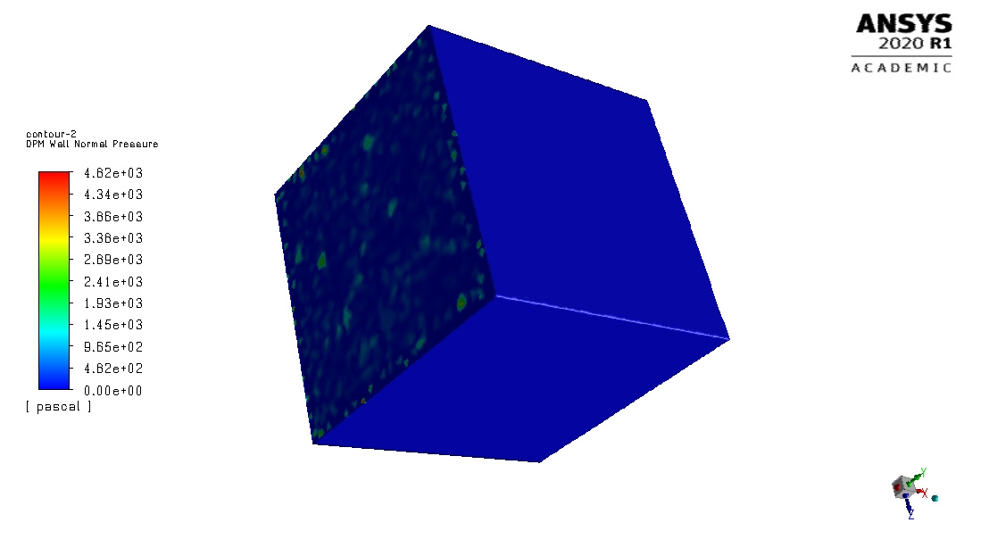 n
Viewing 4 reply threads
n
Viewing 4 reply threads- The topic ‘Rain Modeling’ is closed to new replies.
Innovation Space Trending discussions
 Top Contributors
-
peteroznewman
 6369
6369 -
scabo
 1906
1906 -
Dennis Chen
 1457
1457 -
javat33489
 1308
1308 -
Shyam Prasad V Atri
1022
Top Rated Tags
© 2026 Copyright ANSYS, Inc. All rights reserved.
Ansys does not support the usage of unauthorized Ansys software. Please visit www.ansys.com to obtain an official distribution.
-


The Ansys Learning Forum is a public forum. You are prohibited from providing (i) information that is confidential to You, your employer, or any third party, (ii) Personal Data or individually identifiable health information, (iii) any information that is U.S. Government Classified, Controlled Unclassified Information, International Traffic in Arms Regulators (ITAR) or Export Administration Regulators (EAR) controlled or otherwise have been determined by the United States Government or by a foreign government to require protection against unauthorized disclosure for reasons of national security, or (iv) topics or information restricted by the People's Republic of China data protection and privacy laws.
