-
-
November 24, 2024 at 12:03 am
aagalvez
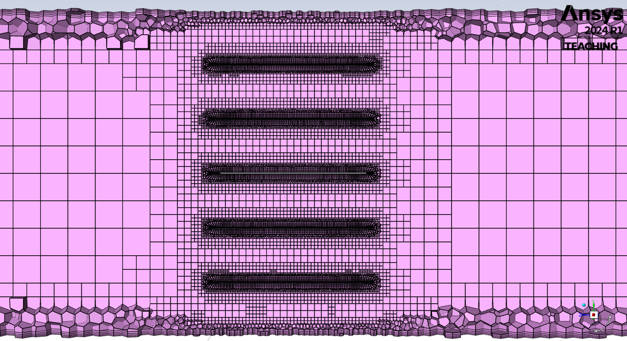
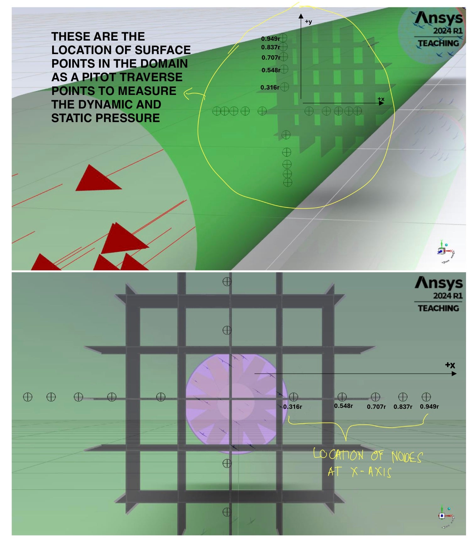
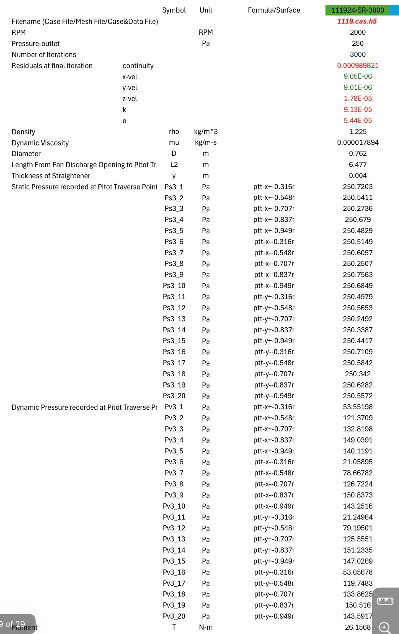
SubscriberI am simulating a system consists of three domains namely stator inlet (stationary zone), rotor domain (rotating zone) and stator outlet (stationary zone). The air intake starts from inlet then flowing it to the outlet domain through the impeller in the rotor domain. The stator outlet domain has a rectifying grid inside of 4 mm thick. The 12 blades of the impeller are 2 mm thick. The hydraulic diameter of the system is 762 mm and the total length of the whole domain is 9701.325 mm from inlet up to the outlet domain. The boundary condition at the outlet is 0 Pa gauge and the outlet BC is 250 Pa gauge. The impeller speed was set to 2000 RPM. I assigned some surface points 6477 mm from the inlet right after the rectifying grid to measure the dynamic and static pressure at these points. These pitot traverse points were assigned at the following points from positive and negative x and y axis: 0.316, 0.548, 0.707, 0.837, and 0.949 of the radius of the system. I run a simulation using the ansys solution but I am getting high dynamic pressure results at 0.949 point surface then becomes lower at 0.316 point surface instead of the opposite. Only to residuals converged by the way as can be seen with the attached results. The whole domain's meshing is also attached and the meshing quality metrics. Why I am not getting the opposite result? Thank you for your help.
-
November 24, 2024 at 12:22 am
aagalvez
SubscriberI assigned the channel of the inlet, rotor and and the outlet domain as moving wall, absolute and rotational and the impeller as a moving wall relative to adjacent cell zone, rotational.
-
November 25, 2024 at 2:38 pm
Petros
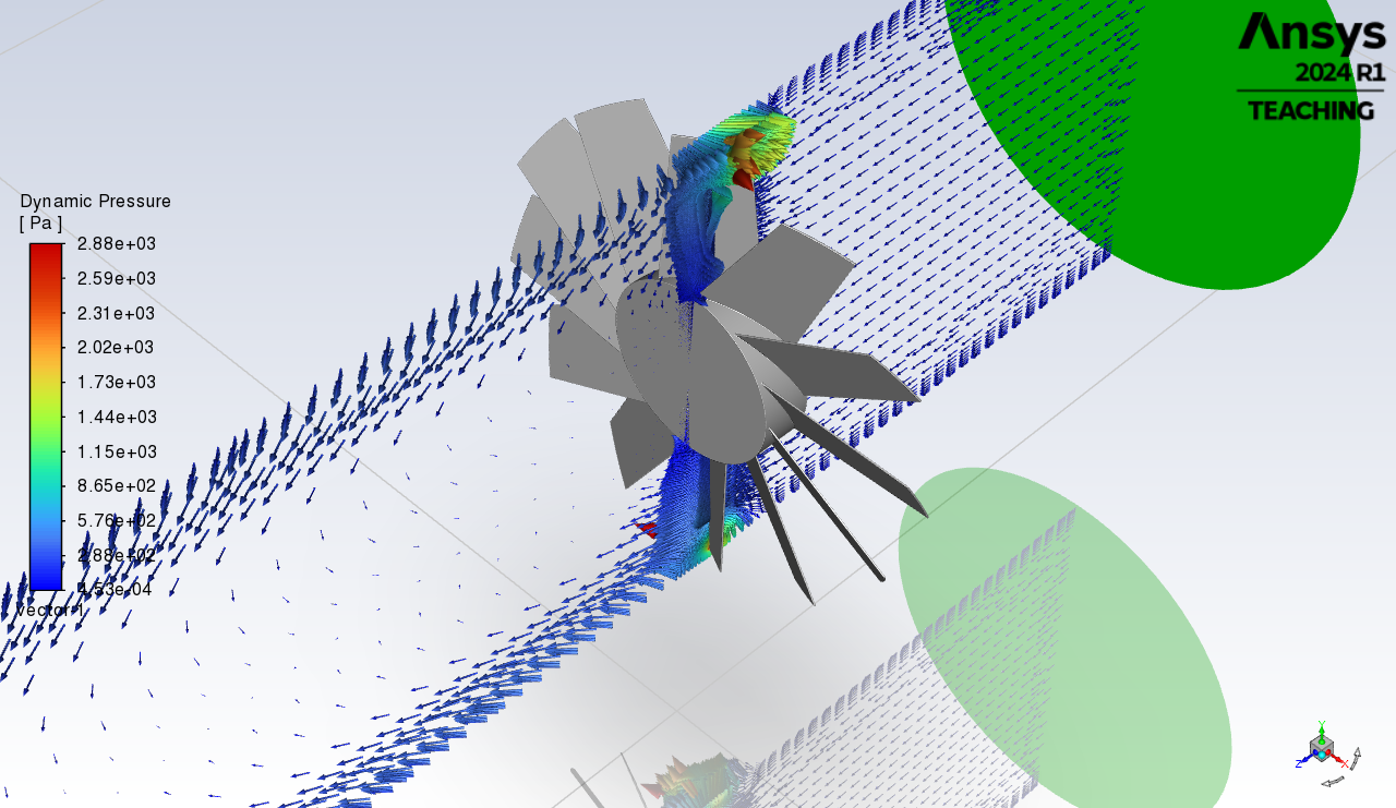
Ansys EmployeeCan this be due to the wake created by the rotor hub? This would mean a slower moving flow in this region, compared to the toroid region after the blades.
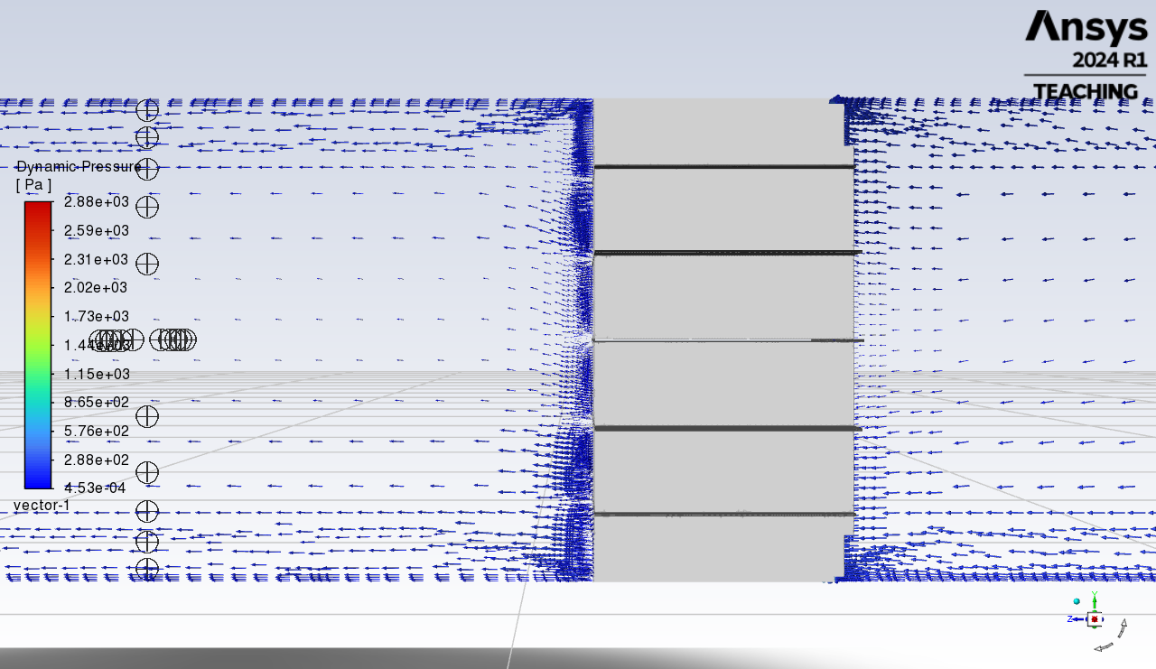
You can do a vector plot on a ZY plane and see how the flow behaves after the impeller.
-
November 26, 2024 at 3:32 am
aagalvez
SubscriberHi, Petros.ill try to capture that and will reply you after my simulation.
-
November 27, 2024 at 10:01 am
-
November 27, 2024 at 11:35 am
Petros
Ansys EmployeeSo it is indeed a slower moving flow at the aft of the impeller hub as can be seen by the smaller in size vectors, which are scaled based on the velocity magnitude. So this can explain the lower dynamic pressure in this region.
Also it seems like you have a higher refinement in the stator inlet rather than the stator outlet. Inlet flow will be mostly undisturbed and uniform while the flow after the impeller will be highly rotating, so maybe a more refined mesh is needed there. -
November 27, 2024 at 11:40 am
aagalvez
SubscriberThank you very much for your suggestion sir. I will refine my meshing in the stator outlet.
-
November 28, 2024 at 3:37 pm
-
- You must be logged in to reply to this topic.


-
3407
-
1057
-
1051
-
896
-
877

© 2025 Copyright ANSYS, Inc. All rights reserved.


