-
-
January 1, 2025 at 11:47 pmnm20004Subscriber
Hello everyone!
I am a beginner in Ansys and I would appriciate it a lot if someone could help me with my problem. I'm modelling a composite overwrapped pressure vessel in Ansys worckbench with a static strucrural analysis. The vessel is cylindrical with hemispherical domes. I have to calculate the radial displacement and the hoop and meridional stress at a specific node at the dome of the vessel. I tried to insert a spherical coordinate system for this purpose but the only available options in static structural are cartesian and cylindrical ones. Please, does somebody know how can i find radial displacement at the node of the below image and hoop and meridional stress at this node and a specific ply? I can't find any information about my problem online.
Thank you in advance for any help!
-
January 2, 2025 at 1:45 pmnm20004Subscriber
Could someone help me please?
-
January 4, 2025 at 4:53 pmClarktSubscriber
You should use shell elements and each element has its own coordinate system that calculates the membrane (hoop) and bending stresses.
D
-
January 6, 2025 at 3:38 pmnm20004Subscriber
Thanks Clarkt for your reply! I created a named selection of the ply in which I want to calculate the meridional and hoop stresses. Then for this named selection I created the element orientations with x axis in the meridional direction and y axis in the longitudinal direction.
Then, I inserted in the solution branch stress->membrane stress. And for the named selection of the ply of my composite I created, I calculated hoop stresses in the local element direction 22 and meridional stresses in the local element direction 11. But the results are not uniform. For example hoop stresses have this kind of distribution.
Do you think that my method is correct, or this ununiform distribution could be caused due to bad mesh or bad definition of the variation of winding angle of the fibers along the dome? If my method is not correct could you please help me?
-
-
January 5, 2025 at 2:13 pmpeteroznewmanSubscriber
Look at the Mechanical APDL command LOCAL on how to define a local coordinate system where you can define a Spherical coordinate system. In that coordinate system, the X axis is the radial direction.
LOCAL
LOCAL,
KCN
,KCS
,XC
,YC
,ZC
,THXY
,THYZ
,THZX
,PAR1
,PAR2
Defines a local coordinate system by a location and orientation.KCN
Arbitrary reference number assigned to this coordinate system. Must be greater than 10. A coordinate system previously defined with this number will be redefined.
KCS
Coordinate system type:
0 or CART
—
Cartesian
1 or CYLIN
—
Cylindrical (circular or elliptical)
2 or SPHE
—
Spherical (or spheroidal)
3 or TORO
—
Toroidal
XC
,YC
,ZC
Location (in the global Cartesian coordinate system) of the origin of the new coordinate system.
THXY
First rotation about local Z (positive X toward Y).
THYZ
Second rotation about local X (positive Y toward Z).
THZX
Third rotation about local Y (positive Z toward X).
-
January 6, 2025 at 4:08 pmnm20004Subscriber
Thank you very much for your help!
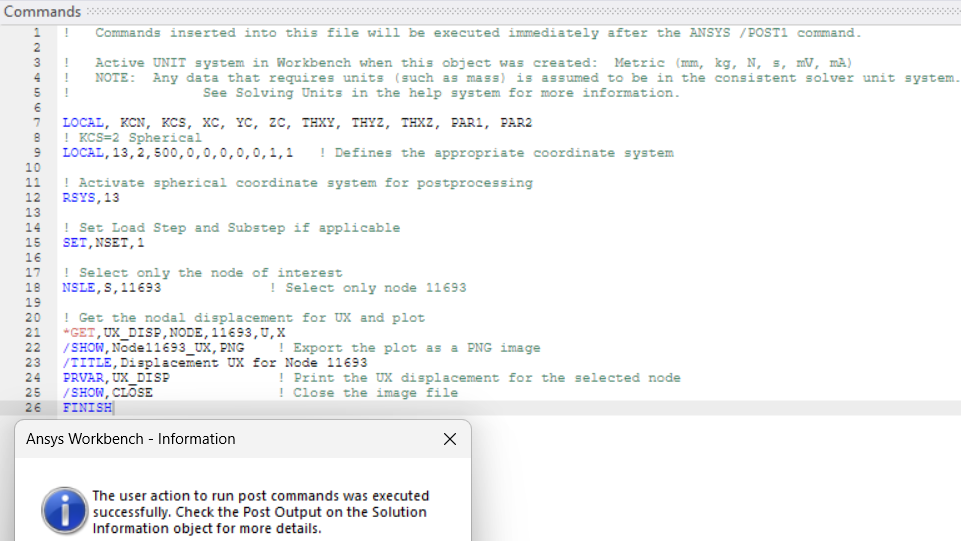
I work on static structural, so I guess I have to insert commands in the solution branch and write a code with the LOCAL command in order to create the spherical coordinate system that I want. But then how can I calculate the radial displacement at the node of my selection? I have to do this with code? I just tried this but a message appears and I don’t get a result.
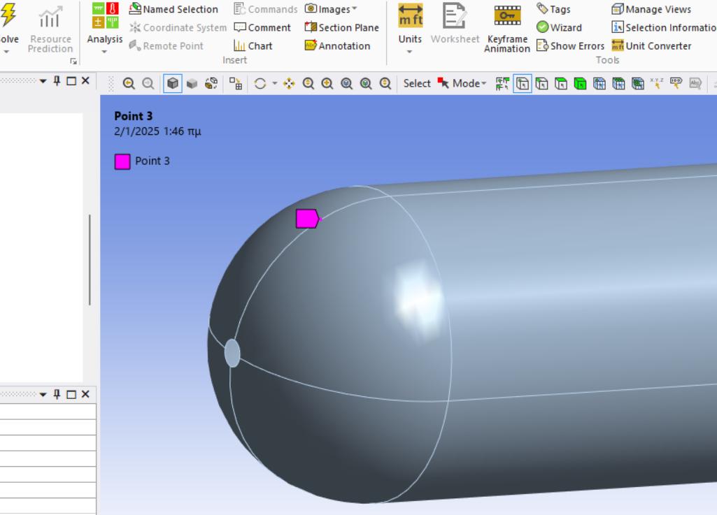
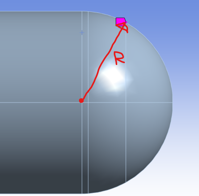
My fial goal is to calculate the displacement of this node in the R direction
I am a beginner in Ansys so if you have such a script, I would appriciate it a lot if you could share it with me.
Moreover, I have one question. Does the deformation object in the solution branch represent the displacement in terms of physics?
-
January 7, 2025 at 1:00 pmpeteroznewmanSubscriber
If you only need the output of a single node, create a rectangular coordinate system and orient the X axis to be along the radial direction. Then you can probe the directional deformation of that one node along the X axis of that coordinate system. In Ansys, they use the term Displacement for boundary conditions which means holding nodes with 0 displacement or requiring them to move along a specific vector. The term Deformation is for the vector from the initial coordinates of the node to the deformed coordinates of the node that was calculated in the solution.
To plot all the nodes, you would need some APDL code, but I am not good at writing that code. I would have to build myself a small model and experiment to advise you further. Maybe someone else will comment.
-
- You must be logged in to reply to this topic.
- At least one body has been found to have only 1 element in at least 2 directions
- Error when opening saved Workbench project
- How to apply Compression-only Support?
- Geometric stiffness matrix for solid elements
- Frictional No separation contact
- Timestep range set for animation export
- Image to file in Mechanical is bugged and does not show text
- Script Error Code:800a000d
- Elastic limit load, Elastic-plastic limit load
- Element has excessive thickness change, distortion, is turning inside out
-
1406
-
599
-
591
-
555
-
366
© 2025 Copyright ANSYS, Inc. All rights reserved.