-
-
November 4, 2024 at 4:32 pm
viliusv
SubscriberHi,
I am modelling a 3D cantilever beam with a point load applied downwards at the end of the beam. The cross-section is hollow square tube (edge length equals 10mm, thickness is uniform and equal to 1.5 mm). The length of the beam is 750mm. For boundary condition, I am using a fixed support applied at the entire cross-section face. The point load is 49.05 N.
The maximum normal stress is as expected at the maximum distance from the neutral axis and equal to 1.36e8 Pa. However, when calculating analytic solution, I get sigma_max = M_max*y/I = 49.05*0.75*(0.01/2)/I = 2.9e8 Pa where I = 6.33e-10 m^4. I believe my issue is direct result of applying the fixed boundary condition incorrectly, so I would appreciate some help.
P.S. My mesh is well-discretized, in length direction 300 divisions, for both the outer and inner surface of cross-section there are 30 divisions on each edge. Also, my deflection at the tip matches the analytic solution.
-
November 4, 2024 at 6:26 pm
Armin
Ansys EmployeeHello,
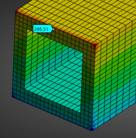
At the other end of the beam, try applying the load to the entire cross section (instead of a point load). I just created a model using Fixed Support at the other end and was able to get the expected ~290 MPa stress (screenshot below). Note that stresses particularly at the corners are not in agreement with the analytical approximation as the simplifyng assumption made to derive this analytical formula leads to this discrepancy.
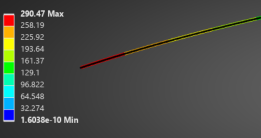
You can also try modeling this 3D model as a line body or “beam” where the resulting stress is also in line with the analytical calculation (picture below).-
November 4, 2024 at 6:45 pm
viliusv
SubscriberThank you. I actually realized my mistake. It was mainly the fact that the stresses displayed were for normal stresses in x-direction whereas the length of my beam and thus normal stress I am interested in is oriented in Z-direction. The answer I get in that case is around 3.29e8, which is close.
Nevertheless, when you say apply the load over the entire cross-section, do you mean to select the entire cross-section face surface when defining force? Or do you mean applying it over the entire top edge (10mm)?
-
November 4, 2024 at 7:09 pm
Armin
Ansys EmployeeThanks for the confirmation.
My impression of your initial post was that you applied the load as a "point load" which is generally not recommended. You can apply the force over an edge which is better than a point load but it is usually recommended to apply forces over a cross sectional area. You can watch the video below where this topic is discussed in more detail.
Understanding and Dealing with Artificially High Stresses — Lesson 3 | ANSYS Innovation Courses -
November 4, 2024 at 11:28 pm
viliusv
SubscriberThank you for your help :)
-
-
-
- You must be logged in to reply to this topic.


-
3472
-
1057
-
1051
-
940
-
902

© 2025 Copyright ANSYS, Inc. All rights reserved.


