-
-
November 30, 2023 at 7:32 am
ANSYS EXPLORER
SubscriberDear Experts,
I am doing a steady state thermal plus structural analysis in ANSYS WORKBENCH & SPACE CLAIM.
The construction is a cylinder build with Shell element, Solid element and mixed of both Elements.
I tried with below three approaches, but NO sucess.
------------------------------------------------------
Appraoch 1 :
Fully applied shared topology.
I enabled beta option in "General mechanical" and " Allow thermal variation along shell thickness". And enabled "Node merge option at edge".
When i run the model, thermal growth (distribution) across shell element side (through thickness or varying over surface) is not achieved. And expected deformation behaviour towards Y axis is not acheived instead FE model deformed at ceter portion.
Appraoch 2 :
Partial shared topology applied. Only on Shell to shell element connection .
Whereas for other connections used solid to shell element , bonded contact with "MPC" formulation and "Distributed,All direction" config. Initial contacts result checked and found okay.
And enabled "Node merge option at edge".
I enabled beta option in "General mechanical" and " Allow thermal variation along shell thickness".
When i run the model, thermal growth (distribution) across shell element side (through thickness or varying over surface) is not achieved. And expected deformation behaviour towards Y axis is not acheived instead FE model deformed at ceter portion.
Appraoch 3 :
Fully bonded contacts used for Shell to shell element connection and shell to solid element connection with "MPC" formulation and "Distributed,All direction" config .
And enabled "Node merge option at edge".
Initial contacts result checked and found okay.
I enabled beta option in "General mechanical" and " Allow thermal variation along shell thickness".
When i run the model, thermal growth (distribution) across shell element side (through thickness or varying over surface) is not achieved. And expected deformation behaviour towards Y axis is not acheived instead FE model deformed at ceter portion.
------------------------------------------------------
As i aware that Solid to shell element connection is not advisible to use shared topology due to element restrictions ( Shell element has 6 DOF whereas Solid element has only 3 DOF).
Question -1 : Kindly advise on what connections are preferable when we use solid to shell element and shell to shell element in FE model.
Question -2 : And also how to achieve the thermal growth (distribution) on shell element side.
Question -3 : Also i am not able to apply different temperature on cylinder which is modeled with shell element ( Example Inside temperature is 450 Deg and outside surface should be 22 Deg OR fully insulated). I tried in Element orientation with various "Z" directions (-Z and +Z) . But no sucess.
Thank you in advance. Hopefully i would get clarified with your expertise.
Regards
AE
-
December 1, 2023 at 3:00 am
ANSYS EXPLORER
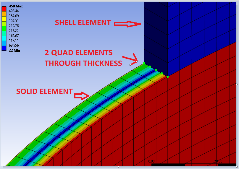
SubscriberIn continuation to above message, i am posting a snapshot taken from ANSYS presentation in the year 2015, it is stating that temperature distribution on shell element through the thickness is not supported and further, it was indicted that temperature "MAY" vary over the surface when we perform thermal analysis. Here, the "MAY" is giving uncertainity on output as per current formulation. Did any one come across this issue ? please share your findings. Further, i digged out in this forum for similar query, but not able to locate . Thank you.
Regards
AE.
-
December 2, 2023 at 1:51 pm
peteroznewman
SubscriberDid you build a model entirely with solid elements and no shell elements? You can use Shared Topology if you need to change properties between the middle and the ends of the tube. Just make sure to use at least 4 linear element or 2 quadratic elements through the thickness.
-
December 3, 2023 at 8:12 am
ANSYS EXPLORER
SubscriberDear Peter,
Thank you for your response.
As described in my above messages, i modelled center cylinder with solid elements and adjoining cylinders (top and bottom) with shell elements. Entire FE model done with shared topology.
I tried your suggestion by adopting “at least 2 quadratic elements through the thickness”, unfortunately no sucess.
The questions are in concern is temperature distribution is not heppening in shell elements. Further, deformation is not heppening in length of the cyclinder , but deformation happening in radial (stress) direction . Why these behaviour happenings in FEA when we join shell and solid lements together against as expectation of longitudinal growth?…
Further, as i referred in my above post on ANSYS 2015 presentation, it is stated that through thickness temperature variation will not happen in shell Elements , and surface distribution “MAY” happen…Is it so?…Did u come across such issues. Awaiting for your advise.
Regards
AE.
-
December 4, 2023 at 7:15 pm
peteroznewman
SubscriberMy suggestion is to not use any shell elements at all.
My suggestion is to use solid elements ONLY.
-
December 5, 2023 at 3:52 am
ANSYS EXPLORER
SubscriberDear Peter,Thank you for your response.This FE model is a prototype of Original equipment. We are trying to optimise the FEA using Solid and shell element combination as we are facing higher computational timming and memory shortages issues when we use SOLID elements fully (ONLY) . If this prototype gets sucess, then we would plan to implement the same on acutal FE model.RegardsAE -
December 5, 2023 at 1:50 pm
peteroznewman
SubscriberAdjust Mesh controls to mesh with 2 or 3 times larger elements on the face of the cylinder while maintaining 2 elements through the thickness. That will reduce the node count by a factor of 4 to 9.
Under Analysis settings, change the Solver Type from Sparse Direct (or Program Controlled) to PCG Iterative. The interative solver needs much less RAM and will often solve much faster than the Sparse Direct solver on a solid element only mesh.
-
December 6, 2023 at 11:51 am
-
December 7, 2023 at 1:06 am
peteroznewman
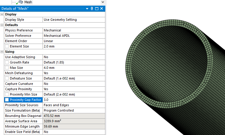
SubscriberHere is a six year old post that tells you how to get 3 elements across the thickness. Six years later, the Mesh details panel has a new look. The Proximity Gap Factor is the number of elements across the thickness. This works for all kinds of complex thin walled geometry.
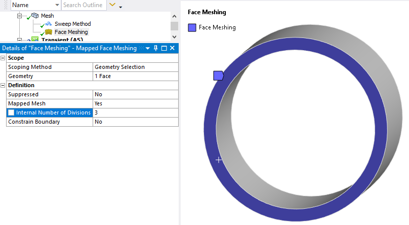
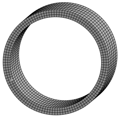
Your geometry is a simple tube, so you can insert a Mesh Method: Sweep and a Face Meshing control where you set the Internal Number of Divisions to 3.
Pick the body and then select the same end face as the source face.
Shared Topology is not going to work with 3 elements through the thickness. The problem is there will not be a row of nodes at the center of the solid element meshed tube. You will be better off not using Shared Topology. Instead use Bonded Contact so that the edge of the surface can be bonded to the face of the solid tube. This will be superior to Shared Topology because the contact elements will support the the rotational DOF of the nodes on the shell elements that a row of nodes at the center of the solid face does not support.
-
December 8, 2023 at 9:41 am
ANSYS EXPLORER
SubscriberDear Peter,
Thanks for your response.
I implemented your sugestion on my original job (Dia 2.5 meter / 15mm thk / 7.8 meter Long having various nozzle connection) and acheived 3 elements across the thickness on solid elements. I used Bonded type contact for face of solid element to edge of shell element. I removed shared topology completely.
I performed Initial contact check, it is not achieved as more than 10 contacts having in orange status showing gaps between the contact bodies. Then i used the pinball adjustment and node merging option to pass the same. The said adjustment gave positive results then i proceeded for full simulation. It took around 4.5 hours to complete the entire run.
After completion of solution, i surprised to see various parts of said FE model are sliding in the animation and expected results (reaction) is not acheived due to this sliding.
I have a doubt since i have established 3 elements across thickness of solid element , so the mid surface do not have nodes to get contact with shell element though i used bonded type contact bewteen face and edge of solid and shell element respectively. Could be the reason ?
Plz advise how to fix this issue as i remeber when i used shared topology this much sliding issues did not happen.
Thank you in advance.
Regards
AE.
-
December 8, 2023 at 11:45 am
peteroznewman
SubscriberPlease reply with the Contact details. Try setting the contact formulation to MPC. Try increasing the Pinball Radius to much larger values. After solving with MPC bonded contact, you can look at the red spider of Contact Elements in the Graphics window to see which nodes are connected. Put an image of that in your reply.
-
December 9, 2023 at 5:50 pm
ANSYS EXPLORER
SubscriberDear Peter,
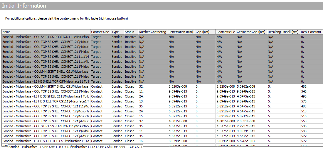
As suggested, I have modified the contact details as below.
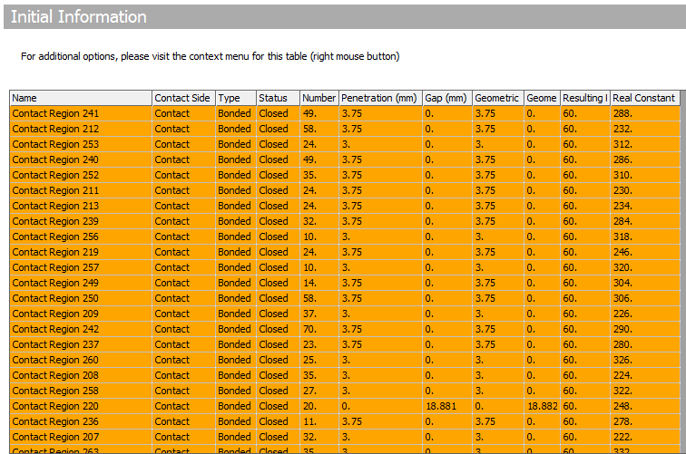
Shell to Shell element – Initial contact check is NOT acheived though i increased the pin ball diameter to twice larger (60mm) with MPC formulation as below.
ANSYS Info - "All contact results of contacts with MPC formulation are zero since constraint equations are used to bond the mesh together. Review results of the parts underlying the contact surfaces for more information". Will this info influence the result?
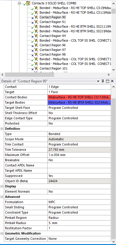
Solid to Shell element – Initial contact check is acheived as i increased the pin ball diamter to 5mm (near by value) with MPC formulation as below.
I am not able to run the further model for solution due to Initial contact check of shell to shell element is not sucess as narrated above.
Please review and advise. Thank you.
Regards
AE
-
December 10, 2023 at 2:29 pm
peteroznewman
SubscriberAE, What version of Ansys and which type of analysis are you in?
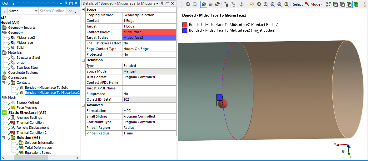
Under your section Solid to Shell element, your image of the bonded contact lists Midsurface objects for both sides of the contact. I would expect to see the Target Body to be listed as a Solid. I also see a Restitution Factor.
I am using 2023 R2 with a Static Structural analysis and my bonded contact of solid to shell shows a midsurface on the Contact side, while it shows a solid on the Target side. It does not show a Restitution Factor.
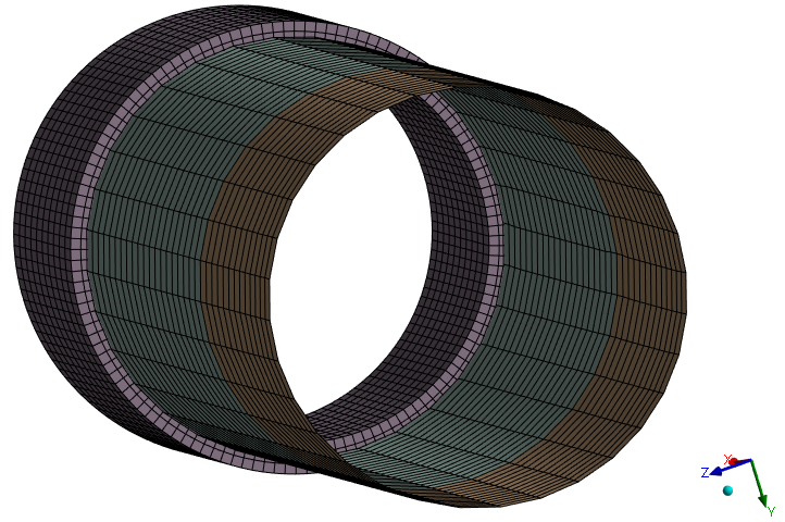
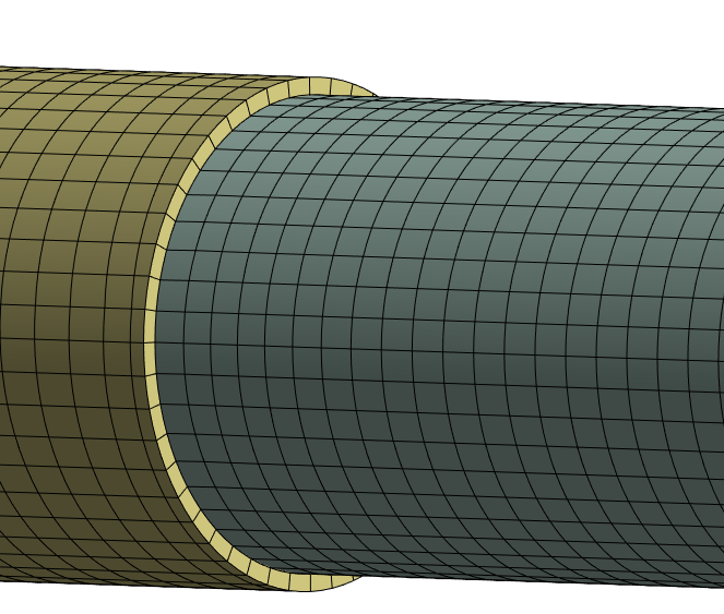
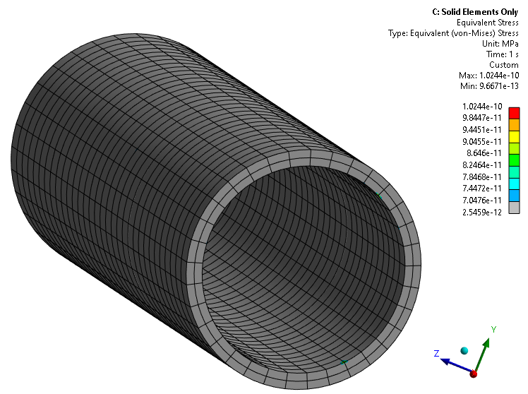
Below is the mesh for my demo model that has one solid tube with 3 elements through the thickness and two midsurface tubes. No shared topology is being used. Two bonded contacts are used to connect the 3 bodies, which all have the same material and all have a uniform temperature load. A deformable Remote Displacement supports the structure.
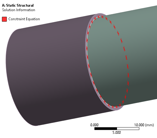
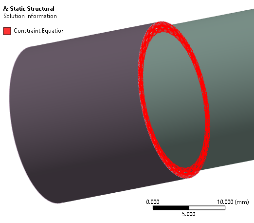
For the Solid to Shell bonded contact, note that the Edge Contact Type I selected is Line Segments in the image below.
Below are the Connection Elements generated.
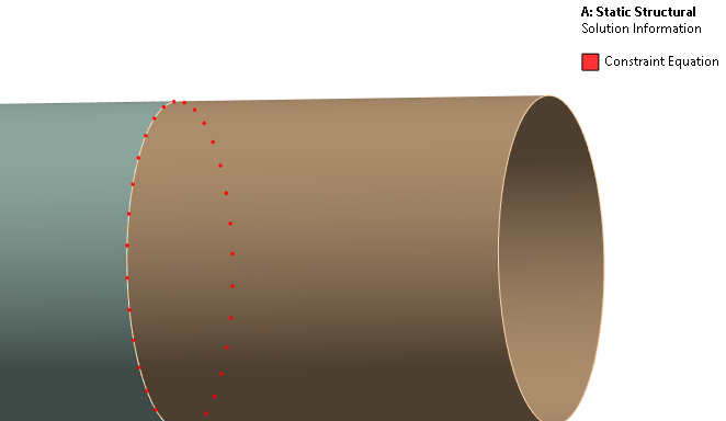
If I change the Edge Contact Type setting to Nodes on Edge, this is the Constraint Equation plot.
For my Shell-Shell Bonded Contact, below are the Contact details.
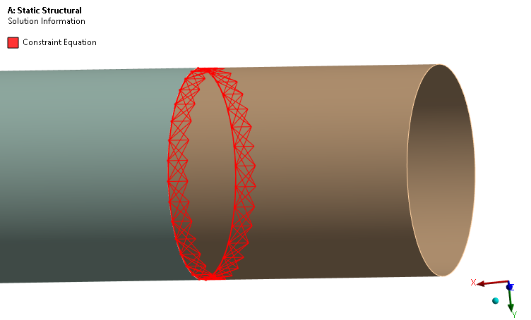
Below are the generated Constraint Equations.
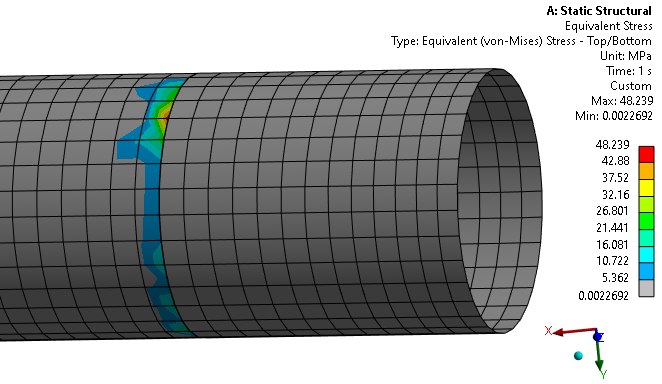
This is undesirable because Constraint Equations are rigid so they cause stress during thermal expansion even when a uniform temperature load is applied to all bodies with the same material.
When the nodes line up, the better Bonded Contact configuration between the shells is Line Segments. Below is the Constraint Equation plot. Notice that the elements have zero length. They are connecting node to node.
Below is the stress plot.
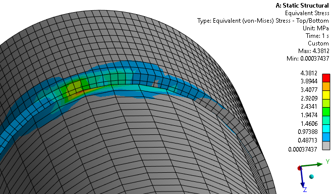
The stress is coming from the rigid elements connecting the Solid to the Shell.
The above is for the Line Segments setting for the bond between the solid face and the shell edge, which generated short rigid elements. Below is the stress for the Nodes on Edge setting which generated longer rigid elements. Notice that the connection that should have zero stress increased from 3.0 to 4.4 MPa.
The switch from shells to solids must be done far from places where there is a significant thermal gradient. The lesson here is that you will need to take some pains to exclude plotting stress on elements near the connection between shells and solids. That can be accomplished by slicing the bodies on each side of a change from shell to solid and removing those bodies from the scope for the stress plot.
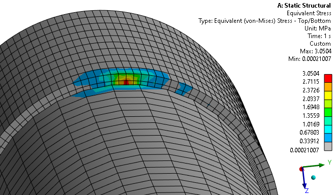
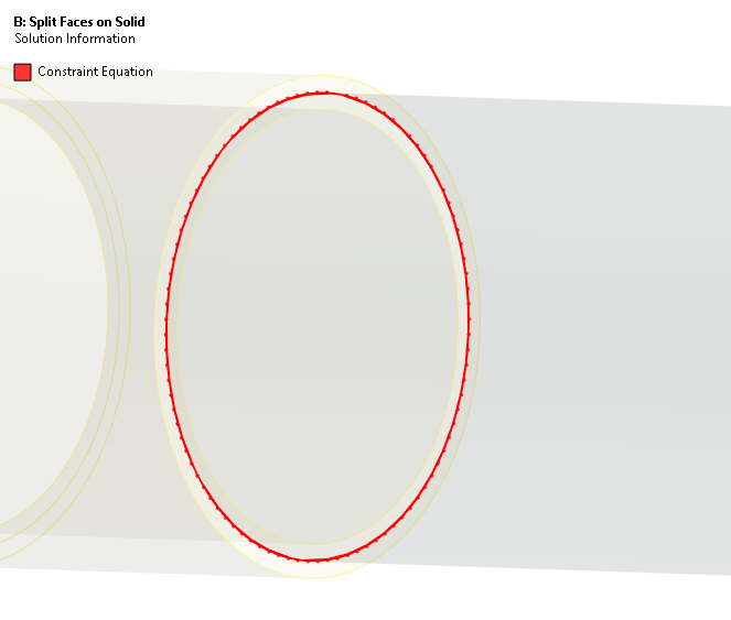
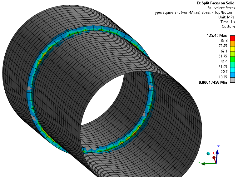
I tried to make only zero length rigid Connection Elements by splitting the face of the solid, changing the Bond to the Edge at the center of the split face instead of Face and using Line Segments. I made the mesh exactly line up, node-to-node. Here I am using 2 quadratic elements through the thickness.
However, the Connection elements are not zero length.
For all that effort, the stress only got much, much worse! I even tried making a Nodal Named selection along the Split Edge. That did not help.
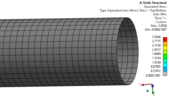
I therefore return to my initial advice at the top of this discussion. Use solid elements only, no shells. Below is the zero stress result.
If the solid element mesh exceeds the capability of the computer, install the maximum RAM the computer can hold. If you are at that limit, and can’t get a bigger computer, you will have to do a lot of work to ignore the unavoidable stresses between shell and solid elements or break the large model into smaller pieces to use solid elements only. For that you can have an all shell global model and use Substructuring to create valid boundary conditions for the submodel that can be all solid elements.
Good luck.
-
December 12, 2023 at 11:50 am
ANSYS EXPLORER
SubscriberDear Peter,
Thanks a lot for your extended support and expetrise.
Yes. we also felt the same to go ahead with SOLID elements only and trying to upgrade to work station at our end. We use ANSYS 2023 R2 version.
"Under your section Solid to Shell element, your image of the bonded contact lists Midsurface objects for both sides of the contact. I would expect to see the Target Body to be listed as a Solid. I also see a Restitution Factor."
- Sorry it was a typo error as i pasted another screenshot by mistake...But actual joint is Target body is listed under Solid only.
Further , we do FE analysis mainly with steady state thermal with structural analysis frequently. The subject FEA also one among them.
For the subject model, i did modal analysis and results found zero frequency for first 4 modes..it shows clearly lot of connections are loosen in it.
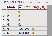
Is there any way find the which are all parts in motion (lossen state) individually in ANSYS Workbench. Please advise.
However, as you said , we are going ahead with complete solid element model for this job parallely after upgrading machine. Thank you.
Regards
AE
-
December 12, 2023 at 12:20 pm
peteroznewman
SubscriberGlad that I was able to show you the issues when using bonded contact between shells and solids in a stress analysis with temperature loads.
The Modal result shown above has six "zero" frequency modes because 4.5e-7 is numerically the same as zero. A common check on the quality of a FEM is to have no connections to ground and request 10 modes. A good result is to have the first six modes be "zero" and mode 7 to be more than 100 times larger than any of the first six modes.
In a model with bonded contacts between many bodies, a modal analysis that is fixed to ground in all 6 DOF can detect if any part has an incomplete bond. If mode 1 is a value much larger than "zero", then it is properly connected. If all six first modes are "zero" and mode 7 is a large value, that means one body that has no connection at all. You find that body in the Details tab for first mode displacement result. It shows the name of the body with the maximum displacement. For this to be helpful, you must have unique names for all bodies. If you have many bodies with the same name, open the geometry in SpaceClaim, select all the bodies in the outline, right click on them and select Rename. SpaceClaim will number all the bodies sequentially. Without that, you can animate mode 1 and look for the part that is floating around. Repeat this process as there may be more than one body unconnected.
-
December 13, 2023 at 11:54 am
ANSYS EXPLORER
SubscriberDear Peter,
Thank you for your valid guidance. Will catch you in some other queries. I am closing this question as "Answered".
RegardsAE.
-
- The topic ‘QUERY ON CONNECTION BETWEEN SHELL TO SOLID ELEMENT AND SHELL TO SHELL ELEMENT’ is closed to new replies.


-
2778
-
965
-
841
-
599
-
591

© 2025 Copyright ANSYS, Inc. All rights reserved.

