-
-
April 19, 2025 at 9:48 am
werv2486
SubscriberHello everyone,
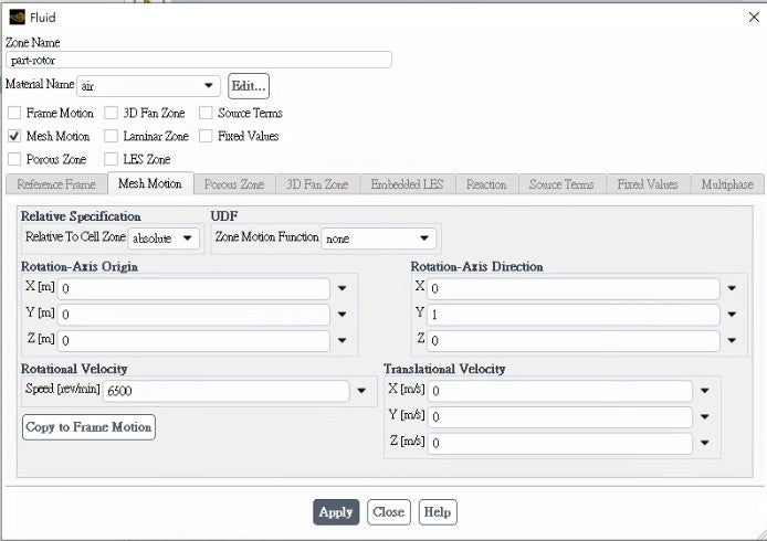
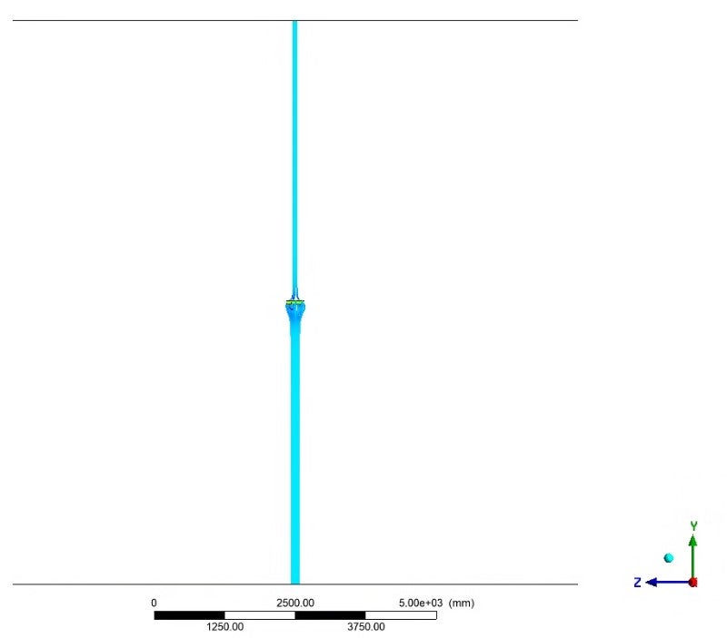
I'm currently working on a transient CFD simulation in ANSYS Fluent 2024 R1, simulating a rotating propeller using mesh motion (rigid body rotation). The setup consists of a rotating domain (260 mm diameter) containing a solid propeller (250 mm diameter), all enclosed within a larger stationary fluid domain (10000 mm diameter).
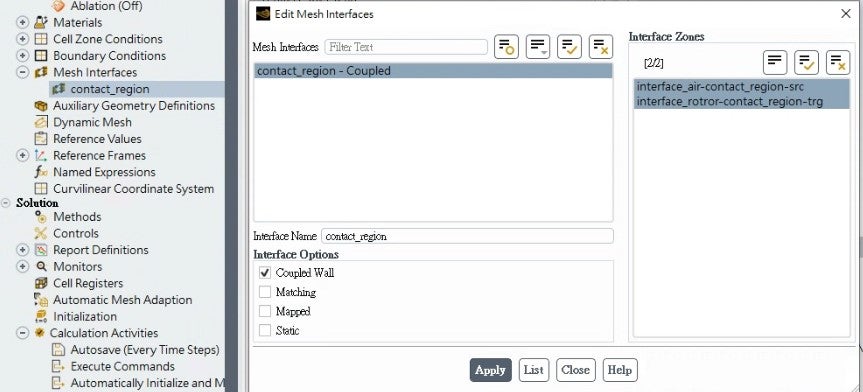
I’m using dynamic mesh motion to rotate the propeller region over time. The interfaces between the rotating and stationary domains are defined with non-conformal dynamic interfaces, and the rotational motion is applied as a rigid body rotation around the central axis.
I'm attaching several images to clarify the setup and issue:
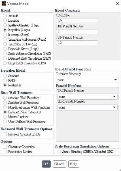
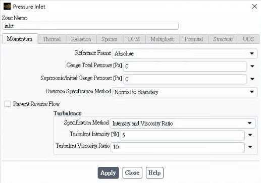
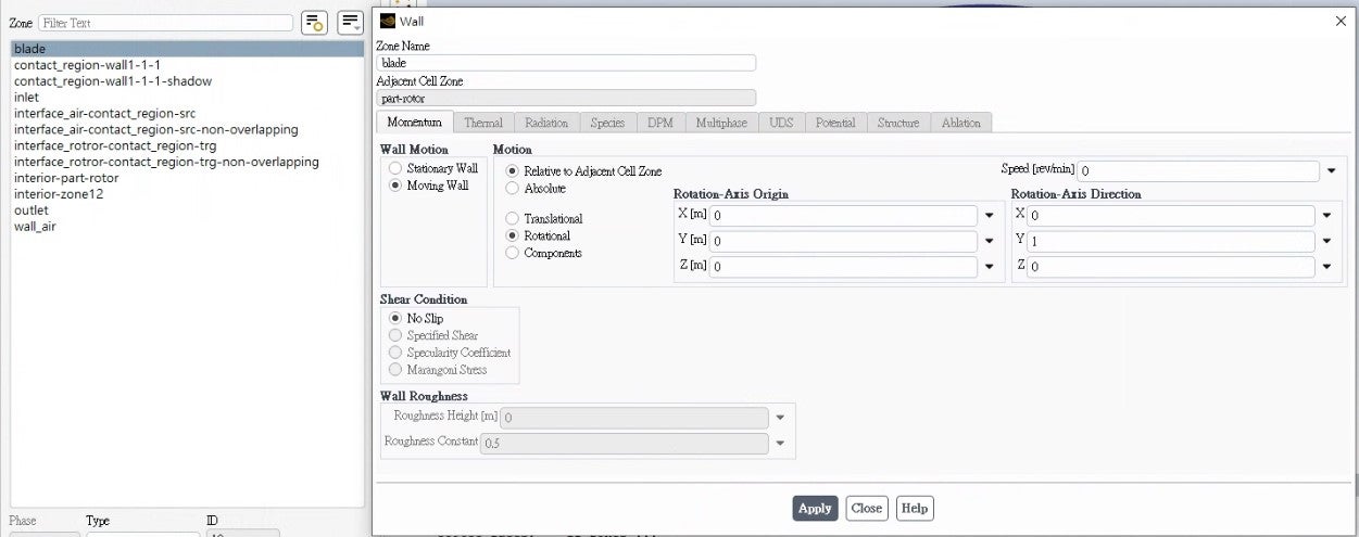
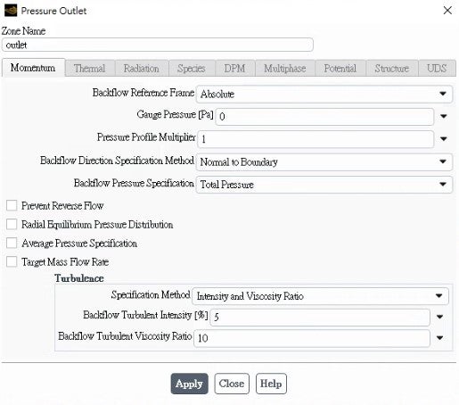
Image 1–6: Fluent setup screenshots (dynamic mesh settings, zone motion, boundary conditions, etc.)
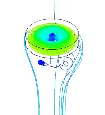
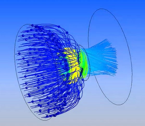
Image 7-8: Absolute velocity streamline plot at a selected timestep (flow pattern looks irregular and unintuitive)
Image 9: A sketch or reference showing the expected flow behavior, especially behind the propeller where vortex shedding is expected
My questions:
Are there best practices when visualizing streamlines in transient simulations using mesh motion?
Should I be plotting streamlines in the relative or absolute reference frame for clearer flow interpretation?
Could this strange flow behavior be due to improper axis definition, dynamic mesh settings, or insufficient time resolution?
Any advice on post-processing or interpreting results for moving mesh simulations would be greatly appreciated.
Thanks in advance for any help!
-
April 22, 2025 at 8:40 pm
Federico
Ansys EmployeeHello,
thank you for including all of these details! It makes any troubleshooting much more efficient.
First, I recommend plotting streamlines in the absolute reference frame. This is the most intuitive formulation for visualization.
Second, if you suspect improper alignement between the defined rotation axis and the actual center of rotation of the propeller, I suggest you create a velocity vector plot in the plan of the propeller (plane defined by the rotation axis) and see if the flow is turning as expected.
Finally, if you are getting good convergence behavior at each time step, then the time step size should not be an issue. Best practices would have the motion of the interface slide by 1 cell length per time step (for 1st order methods) or half that for 2nd order methods.
-
- You must be logged in to reply to this topic.


-
3019
-
970
-
857
-
761
-
599

© 2025 Copyright ANSYS, Inc. All rights reserved.

