Photonics

Photonics

Topics related to Lumerical and more.

Program Termination Error in Charge

    • sumit.20dr0152
      Subscriber

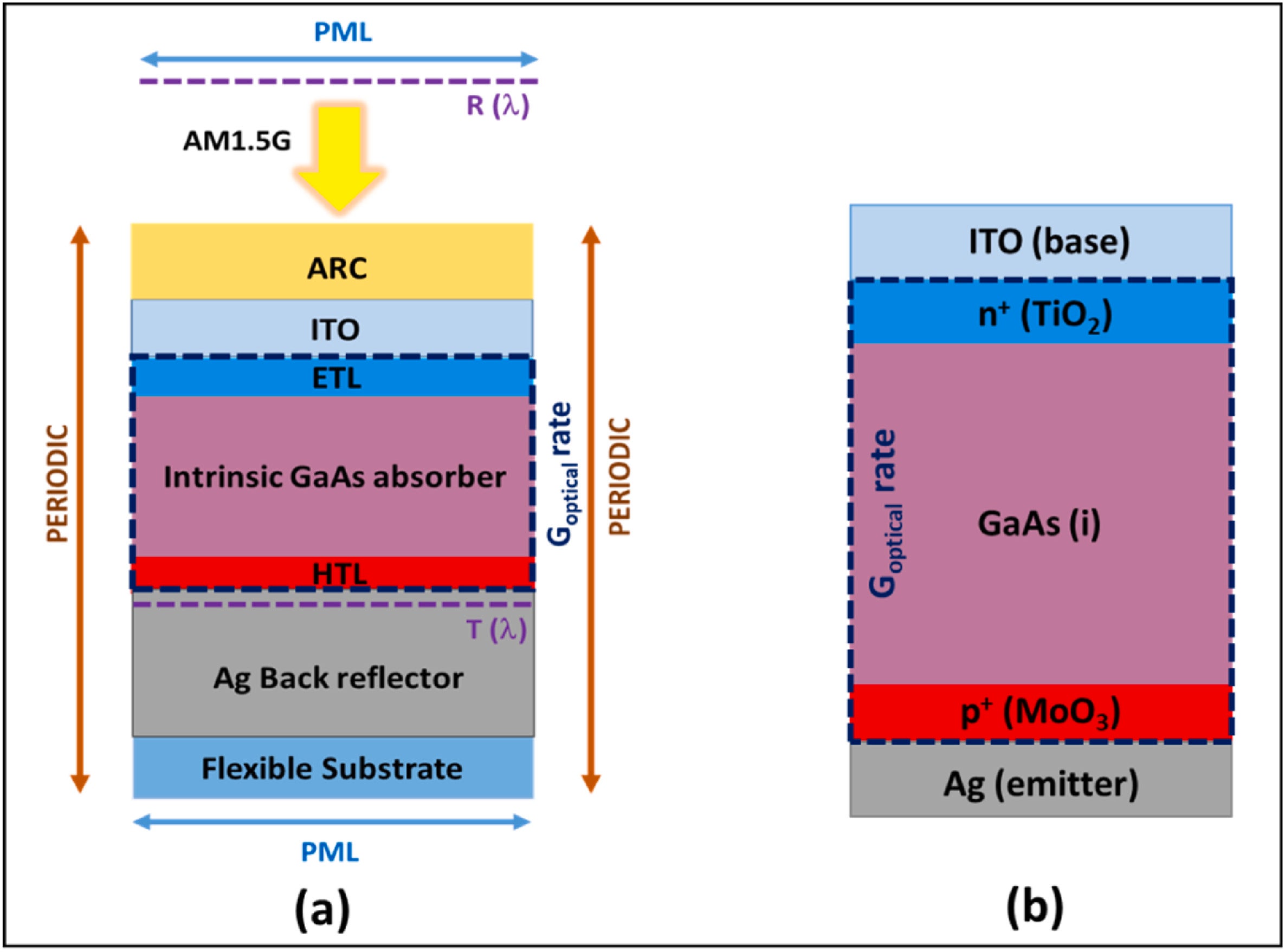
      I am trying to design and simulate the above solar cell structure with FDTD and CHARGE module, with the following layers:

      • TiO2 (10 nm): Electron transport layer (ETL), doped n-type (3e+19 cm−3).
      • GaAs (290 nm): Absorber layer, lightly doped p-type (1e+16 cm−3).
      • MoO3 (10 nm): Hole transport layer (HTL), doped p-type (1e+19 cm−3).

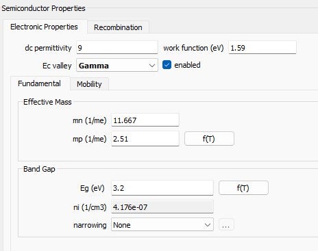
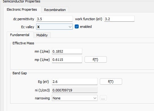
      The semiconductor properties are defined as:: TiO₂: Data from Fig. 2.MoO₃: Data from Fig. 3.

      I successfully simulated the structure in the FDTD module and generated the optical generation file (.mat) with mesh order = 2. However, while running the simulation in CHARGE, I encountered the following errors:

      DESKTOP-URS3EQ3(process 0): The program terminated due to an error: Initialization failed to converge charge update. For instructions on how to troubleshoot this issue, please refer to this: online reference
      DESKTOP-URS3EQ3(process 0): Error: there was an unknown parallel error. The error code is 9002, the process number is 0

      I tried every possible combination from this link: https://optics.ansys.com/hc/en-us/articles/8355464963987-Troubleshooting-convergence-errors-in-CHARGE

      Request for Assistance:

      • Are there specific parameter adjustments (e.g., mobility models, recombination rates, or solver settings) recommended for this structure?
      • Should I consider modifying the mesh or doping profiles for thin layers like TiOâ‚‚ and MoO₃?
      • How can I resolve the initialization convergence error effectively?
    • kghaffari
      Ansys Employee

      Hi,

      Thank you for posting your question and providing detailed information. Since the more general instructions in the troubleshooting article haven’t been helpful, I can provide some specific suggestions, given the description of your problem. These will be modifications to identify the cause of error:

      • Material bandgap: Convergence issues in CHARGE are more common for materials with wide bandgap. Can you try switching TiO2 and MoO3 to a material with smaller bandgap like silicon and run again? If the issue is related to the material, please ensure that the latest version of CHARGE is installed (2024R2) as we have made some improvements to convergence behavior for these materials recently.
      • Mesh: As you suggested, I recommend testing different mesh values. Both increasing or decreasing the mesh refinement may be helpful. I would also test having local mesh objects targeting the two materials you mentioned (TiO2 and MoO3). However, please ensure that the change in mesh settings takes effect in the actual generated mesh. You can mesh (before running) the simulation and see if the numbers are making an impact. If not, try increasing max refine steps.
      • Doping: Please switch the simulation to partition mode and select each doping object, to ensure the doping is applied to the intended region. The region of interest should be both included in the green box (defined by the doping object coordinates) and highlighted (impacted by Applicable Domain>volume type). Applying increased mesh refinement to areas with higher doping can be helpful.
      • Imported generation: If the input power is very high convergence in CHARGE becomes more challenging. You can test reducing the scaling factor in the import object to examine its effect on convergence. Of course, if you are sure that the scaling factor corresponds to the operating input power of your device (and simulating with a smaller number is not helpful) you would need to keep the number. Still, knowing the impact of scaling factor can be helpful here.
      • Initialization Error: I believe this is mentioned in the referenced article; starting the CHARGE simulation from a voltage other than zero makes the convergence more difficult to obtain. Please make sure the starting voltage is 0 and then sweep to your target bias value.

      Hope these can be helpful. Please feel free to follow up with any updates. Best, Khash

    • sumit.20dr0152
      Subscriber

      Hi Khash,

      Thank you for your detailed response and suggestions. I have carefully tried all the recommended steps, but unfortunately, the issue persists, and I am still encountering the same error. Here is what I have observed so far:

      1. Material Bandgap: I changed TiO₂ and MoO₃ to Al(0.8)Ga(0.2)As and Al(0.3)Ga(0.7)As, respectively, as suggested. While this allowed the simulation to run without errors, it does not represent my actual device structure, so it doesn’t fully address the issue with my specific model.
      2. Mesh Refinement: I experimented with both increasing and decreasing the mesh refinement and added local mesh objects targeting TiO₂ and MoO₃. The error remained despite ensuring the changes were reflected in the generated mesh.
      3. Doping: I verified the doping objects in partition mode and ensured they were applied to the intended regions. I also increased mesh refinement in areas with higher doping, but this did not resolve the problem.
      4. Imported Generation Profile: I tried using the reduced scaling factor in the import, but the issue still persists. When I tried running the model with the solar generation profile and adjusted the thickness of Al(0.8)Ga(0.2)As and Al(0.3)Ga(0.7)As to 10 nm (matching my ETL and HTL setup) in this (https://optics.ansys.com/hc/en-us/articles/360042160334-Thin-film-GaAs-solar-cell) model, the simulation ran without issues. 
      5. Initialization Error: I confirmed that the starting voltage is set to 0 and swept up 1.5 volts with a step size of 0.01. Unfortunately, this did not change the outcome.
        If you have any additional insights or troubleshooting steps, I would greatly appreciate your guidance.
        Thank you again for your help!
    • kghaffari
      Ansys Employee

      Hi,

      Sorry to hear the issue persists. Just to confirm my understanding on point 4, in the model that works from this example, are the materials changed to have wide bandgap (like TiO2) or are the materials the same as used in the example? 

      Otherwise, it seems that the issue is due to the difficulty of obtaining convergence for wide bandgap materials. Here are my follow up recommendations:


      • Please make sure the software is updated to the latest version (2024R2). We have introduced improvements to convergence behavior for wide bandgap materials a few versions ago.
      • Please test adjusting the Initialization in CHARGE advanced settings. Try decreasing or increasing the init step size in case it can help finding a solution.
      • Have the global iteration limit set to a number larger than default, e.g. 100 vs the original 40.
      • Try turning off any recombination models in your TiO2 and MoO3. Also make sure the KdotP model is turned off. 
      • We have an online example here, where the simulation of wide bandgap material (LiNbO3) works without convergence issues. Please inspect the CHARGE settings in that simulation in case having some of the same settings can resolve the error.


      Hopefully, these can help resolve the issue. In any case, please let us know here so we can track the problem and release a fix if possible. Best, Khash

Viewing 3 reply threads
  • You must be logged in to reply to this topic.