-
-
April 30, 2024 at 3:31 pm
dubey
SubscriberI need to calculate propagation loss (at 1310 nm) in waveguide of dimension 300 nm height and 700 nm width with core index 1.952 and cladding using top and bottom oxide of silicon dioxide palik. See attached figure for the detail. I am using PML boundary condition in all direction. The apparently after running the FDE simulation the propagation loss COMES TO BE VERY HIGH of 45 d
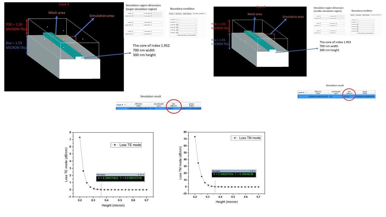 b per cm and as I am increasing the area of simulation region the propagation loss is going to very high value of more than 130 db per cm. Should the simulation area affect the propagation loss value.? Also at sufficiently large area of simulation region the propagation loss is dropping to near zero value, which is again unrealisticaly low value. Please help me sort out the problem. Thank you very much!
 -
April 30, 2024 at 7:14 pm
Guilin Sun
Ansys Employee -
May 1, 2024 at 8:44 am
dubey
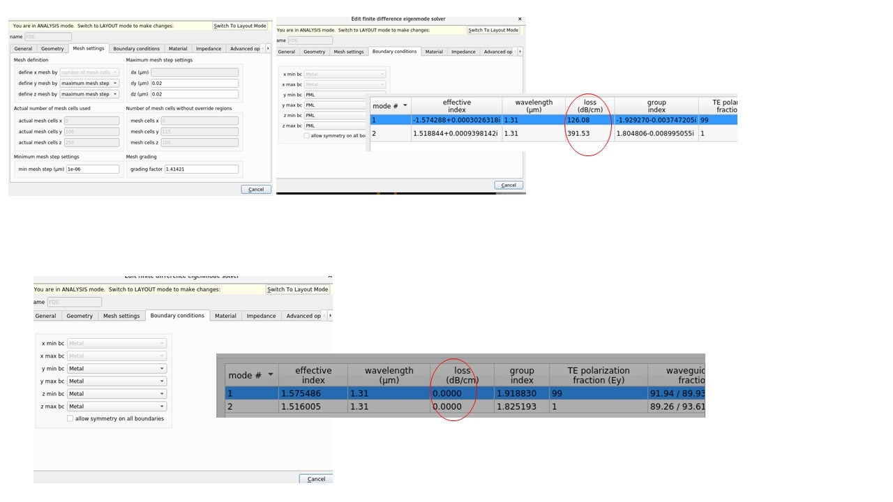
SubscriberI have corrected the mesh size value but still same problem . However, I noticed If I change the boundary condition to metal from PML then the loss is zero. Could it be possible that that simulation is assuming loss due to PML boundary around the waveguide as propagation loss within the waveguide itself?
-
May 1, 2024 at 3:19 pm
Guilin Sun
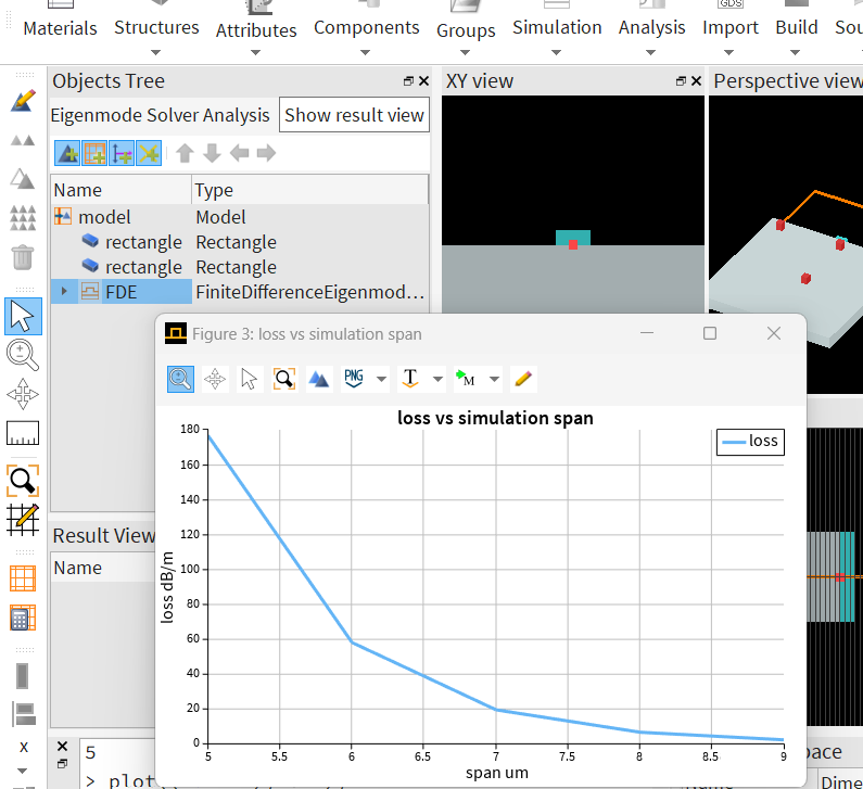
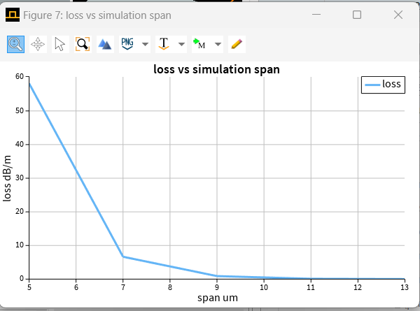
Ansys EmployeeWhen material does not have loss and the guide mode is confined, the simulated loss is from the PML. This is why when I sweep the simulation spans, the loss continues to decrease. PML is part of the mode calculation. You do not need to use very fine mesh in FDE. you can use finer mesh for the waveguide core. and use fixed mesh sizes but use larger simulation area to let the PML be away from guided modes. You can use log scale to check the mode profile and see how much the intensity is at the edge of the simulation region.
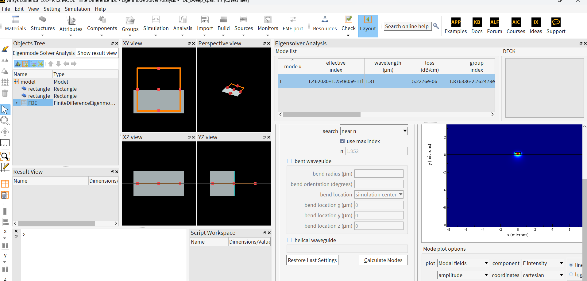
I used 16x16 area with 0.02um, and got this:
If you want to get accurate result at the final stage, you can use larger area and relatively small mesh size.
-
May 1, 2024 at 3:20 pm
Guilin Sun
Ansys EmployeeTo save your time, if you believe a guided mode should not have loss, you can simply use Metal BCs.
-
May 3, 2024 at 10:51 am
dubey
SubscriberThank you very much, that clears my doubt.
-
- The topic ‘Problem in Waveguide propagation loss calculation’ is closed to new replies.


-
3442
-
1057
-
1051
-
917
-
896

© 2025 Copyright ANSYS, Inc. All rights reserved.

