Hello,
Thanks for the detailed explanation. This is a complex problem, so it may be difficult to narrow down the source of the error. If I understand your approach correctly, you are using FDTD (either directly or with field stitching) to obtain the near field some distance above the metalens, and then you use farfieldexact3d to calculate the far-field. Is that correct?
It will be beneficial, if possible, to narrow down whether the issue is occurring in the calculation of the near field or in the calculation of the far field. As a first step, I would recommend using a movie monitor or frequency domain field profile monitor to record a cross-section of the field as it propagates and look for any unexpected behavior.
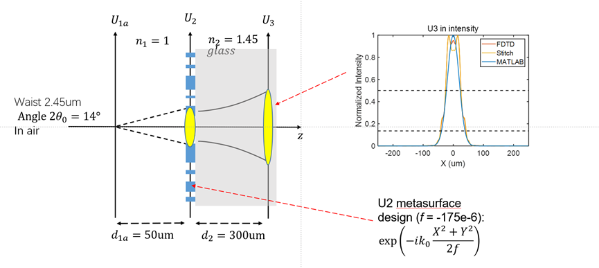
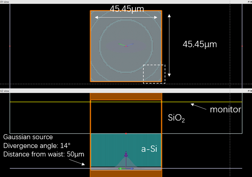
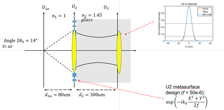
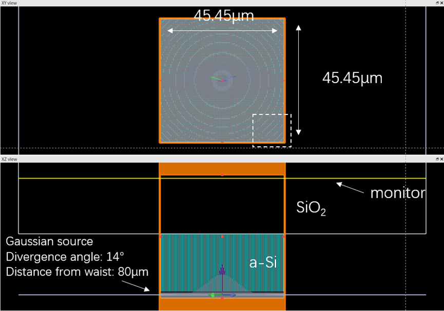
Since your metasurface is a diverging lens, it is spreading the light out to the boundaries of the simulation – is that right? Therefore, if there are any issues with the boundaries, they may be more pronounced in the case of this lens than the typical metalens. Are you using PML boundaries on all sides of the simulation? Since light may be directed to large angles, I recommend using the ‘steep angle’ PML profile. You can also try increasing the number of PML layers.
At the plane U2 where the far-field is calculated, does the field profile extend all the way to the edges of the monitor? It may be beneficial to use a slightly larger simulation region (in x and y) to try to mitigate any edge effects. My initial suspicion is that simulation boundary conditions may play a role in the results you are seeing. If the field is not interacting with the boundaries, then we will have to look for other explanations.
Best,
Anna